The single number that governs PPR in a tower is static head. Water standing in a vertical riser adds roughly 1 bar for every 10 metres of height, so a riser fed from a basement plant room and running to level 30 is carrying nearly 10 bar of static pressure at the bottom before a single pump is switched on. That is why the same PPR pipe that is entirely routine in a two-storey house has to be re-thought for a high-rise: not because the material changes, but because pressure, temperature and movement all stack up with height. This guide sets out the design considerations that actually decide whether a PPR riser works — pressure zoning and PN class selection, thermal expansion over long vertical runs, support and guide spacing, penetrations and fire-stopping, and the documentation a consultant should expect in the submittal.
A note on scope. Everything technical below is general industry guidance for polypropylene-random systems, drawn from common practice and publicly available standards such as DIN 8077 / DIN 8078 and ISO 15874. It is not a WARMHAUS-specific specification and does not replace the project’s own hydraulic calculation. Always confirm against the datasheet of the pipe you are installing, the local code, and the pressure and temperature regime the consultant has specified — a tower riser is engineered, not selected from a blog table.
I. Why Height Changes the Problem
Low-rise plumbing forgives a lot. Runs are short, static head is negligible, and if the pressure class is one step conservative nobody notices. A tower removes that slack in four distinct ways.
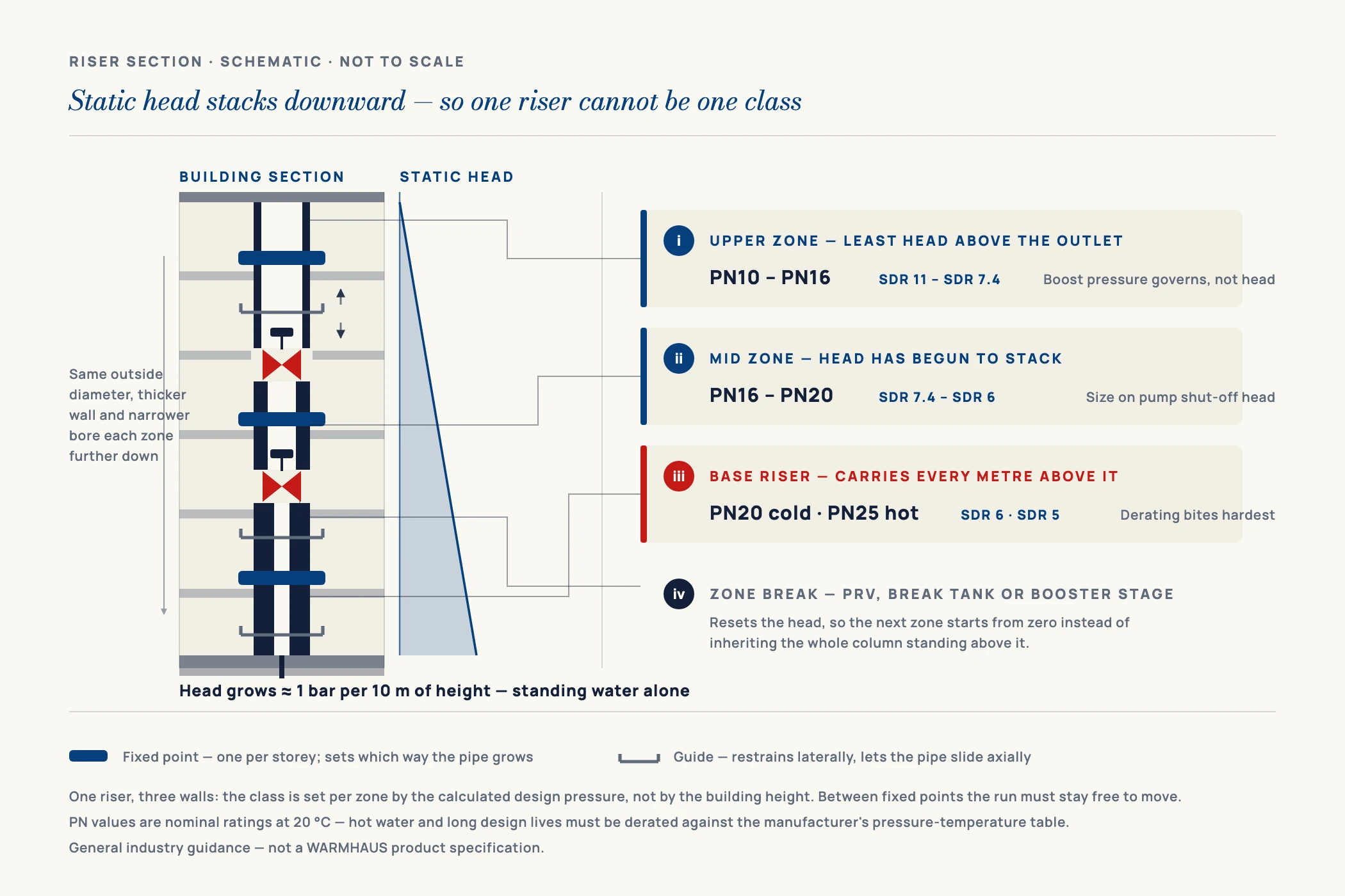
Static head accumulates. Every metre of vertical rise adds about 0.098 bar, so the pressure at the base of a riser is the pump or mains pressure plus the column of water above it. A down-fed system from a roof tank behaves the same way in reverse: the lowest fixtures see the highest pressure. Hence pressure zones, rather than one continuous riser.
Temperature derates the pipe. A PN rating on PPR is nominal at 20 °C. Run the same pipe at 60 °C or 70 °C for a design service life and the allowable working pressure falls substantially. In a tower the hot riser is simultaneously the hottest and — near the base — the most highly pressurised pipe in the building, and those two derating effects multiply. That is why hot risers routinely sit one or two PN classes above the cold risers beside them; the underlying dimensional data is in our reference on PPR pipe specifications.
Thermal expansion becomes a real dimension. As general guidance, plain PPR has a linear expansion coefficient in the order of 0.15 mm per metre per °C; reinforced constructions cut that substantially, glass-fibre types by roughly two thirds and aluminium-layer composites by more, as set out in section III. On a 3 m floor-to-floor pipe with a 40 °C swing that is a few millimetres. On a 30 m riser section it is movement that will pull a bracket out of a wall if it has nowhere to go.
Every slab is a fire compartment. A riser through thirty slabs makes thirty penetrations, each a compartment breach that must be sealed back to the slab’s rating. For a thermoplastic pipe that generally means an intumescent device rather than mortar alone, because the pipe will soften and collapse in a fire.
A tower riser is not a long pipe. It is a stack of short pipes, each one carrying a different pressure, and each one needing somewhere to move.
II. Pressure Zoning and PN Class Selection
Pressure zoning is the first design decision and it constrains everything after it. Rather than let static head accumulate over the full building height, the system is divided vertically into zones, each fed by its own break tank, booster set stage or pressure-reducing valve. Zoning keeps the pressure at every outlet inside a usable band, and it lets the designer choose a proportionate pipe class per zone instead of specifying the worst case everywhere.
The zone height is a calculation, not a floor count. It falls out of dividing the pressure window the code allows at the outlet — the gap between the minimum flow pressure a fixture needs and the maximum static pressure the code permits at a tap — by the static head per storey, which is floor-to-floor height × roughly 0.098 bar per metre. Both ends of that window vary by jurisdiction: maximum permitted outlet pressure is set by the applicable plumbing code and differs enough between countries to move the resulting storey count well outside any rule-of-thumb band, and floor-to-floor height differs between a residential tower and a hotel. Work the division for the project’s own code and storey height rather than importing a number from a guide. If a heuristic is wanted as a first sketch before the code is checked, mid-rise residential zones frequently land somewhere around eight to twelve storeys — but that is an observation about typical outcomes, not an input, and it must not survive into the design once the actual pressure window is known.
The table below shows how static head builds with height and where the common PPR classes typically land. Read it as a way to understand the relationship, not as a selection chart: the actual class must come from the project’s calculated design pressure — including pump shut-off head and surge allowance — combined with operating temperature and design service life. The hot column is where projects most often under-specify. The PN-to-SDR geometry behind these classes is set out in our reference on PPR pressure ratings and PN classes.
| Zone position | Approx. height below zone top | Static head only | Typical cold riser class | Typical hot riser class | Design note |
|---|---|---|---|---|---|
| Upper zone | 0–20 m | ~0–2 bar | PN10 – PN16 | PN20 | Pump/boost pressure dominates over static head |
| Mid zone | 20–40 m | ~2–4 bar | PN16 | PN20 | Check pump shut-off head, not just running pressure |
| Lower zone | 40–60 m | ~4–6 bar | PN16 – PN20 | PN20 – PN25 | PRV commonly introduced at zone break |
| Base / plant riser | 60–90 m | ~6–9 bar | PN20 | PN25 | Temperature derating and surge both critical |
| Hot recirculation | any | as above | — | PN20 – PN25, fibre-composite preferred | Continuous elevated temperature; expansion control essential |
Values are general industry guidance, not a WARMHAUS-specific specification. Static head is calculated at roughly 0.098 bar per metre of water column; PN classes shown are indicative of common practice and must be confirmed against the project’s hydraulic calculation, the operating temperature regime, the required service life and the local code. Always follow the technical datasheet of the pipe you are installing.
Two practical points sit behind the table. First, size the class against pump shut-off head, not running pressure — a booster set at dead-head presents a materially higher pressure than the duty point, and this is a common cause of specifying one class too low. Second, hot recirculation circuits deserve their own decision: they run at elevated temperature more or less continuously, the harshest duty in the building for a thermoplastic, and fibre-composite PPR is widely preferred there. Where a project team is still weighing the riser material itself, our comparison of PPR against PEX, copper and PVC covers the trade-offs.
III. Thermal Expansion on Vertical Runs
This is where high-rise PPR most often goes wrong, and the failure is not dramatic — it is a slow ratcheting of brackets, a bowed riser between two rigid points, and eventually a stressed or fractured fitting. Expansion length is coefficient × pipe length × temperature change; what makes a tower different is simply that the unbroken run is long.
A designer absorbs that movement three ways, and a real riser normally uses all three: expansion loops or offsets formed from the pipe itself, proprietary expansion joints, and — most importantly — a deliberate pattern of fixed points and guides telling the pipe where it may move and in which direction. A riser with brackets clamped tight everywhere has no expansion strategy; it has thirty fixed points fighting each other.
Before the arithmetic, one distinction the industry routinely blurs: “fibre-composite” covers two different constructions that do not behave the same way. A glass-fibre-reinforced PP-R pipe carries a middle layer of PP-R compounded with chopped glass fibre; it reduces expansion but does not eliminate it. An aluminium-layer composite (PP-R/Al/PP-R, sometimes called stabi pipe) carries a continuous metal layer, and metal restrains the polymer far more effectively. The two land in different parts of the range, so quoting a single combined figure and then multiplying it over a 30 m riser is exactly how a loop allowance ends up wrong. Take the coefficient from the datasheet for the specific construction offered, not from the word “composite” on a quotation.
| Item | Plain PPR | Glass-fibre reinforced | Aluminium-layer composite | Notes |
|---|---|---|---|---|
| Linear expansion coefficient | ~0.15 mm/m·°C | ~0.05–0.06 mm/m·°C | ~0.03 mm/m·°C | Metal restrains axial movement more than chopped fibre does |
| Movement, 10 m run, ΔT 40 °C | ~60 mm | ~20–24 mm | ~12 mm | Illustrative arithmetic, not a design value |
| Movement, 30 m run, ΔT 40 °C | ~180 mm | ~60–72 mm | ~36 mm | Requires loops, joints or planned offsets |
| Fixed point interval | Typically one per storey or per zone segment | Defines the direction movement is pushed | ||
Values are general industry guidance, not a WARMHAUS-specific specification. Expansion coefficients vary between products, reinforcement constructions and manufacturers; the figures above are indicative ranges from common industry practice, and the movement rows are simple coefficient × length × ΔT arithmetic shown to illustrate scale. Always confirm against the technical datasheet of the exact pipe construction you are using, and against the project’s mechanical design.
Support spacing is the other half of this and it belongs to one table, not to every article that touches it. Intervals for PPR fall as temperature rises, and vertical riser spacing runs roughly 1.5 to 2 times the horizontal figure for the same diameter, because a riser is carrying its load in axial compression rather than bending. Wall thickness matters as much as diameter here — a Ø63 mm pipe in PN10 and the same Ø63 mm in PN25 do not have the same stiffness and will not take the same bracket interval, so read the spacing table together with the class you actually specified. The full interval-by-diameter and by-temperature figures are in our reference on PPR pipe clips and support spacing; use that table rather than a second one here.
In practice the cleanest riser detail is the simplest: a fixed point immediately below or above each floor penetration, guides between fixed points that restrain the pipe laterally but let it slide axially, and a designed offset or loop where accumulated movement has to be taken up. Branch tees should be arranged so the branch is not acting as an accidental anchor.
IV. Riser Detailing, Penetrations and Acoustics
Three detailing issues recur on every tower and none of them are about the pipe material itself. They are about what happens where the pipe meets the building.
Slab penetrations and fire-stopping
Each floor crossing breaches a compartment and has to be reinstated to the slab’s fire rating. Because PPR is thermoplastic and will soften and collapse under fire, this generally calls for an intumescent collar or wrap sized for the pipe diameter, installed to the manufacturer’s tested detail — not mortar or foam alone. Design point: confirm the fire-stop product is tested for the specific pipe material, diameter and slab construction, and that the sleeve arrangement still permits the axial movement your expansion strategy requires.
Sleeves, guides and the fixed-point pattern
A sleeve through a slab is not a support and must not become one by accident. It should guide the pipe, not grip it. Design point: mark fixed points explicitly on the riser drawing rather than leaving bracket type to the installer — a riser detailed on site tends to end up over-anchored, which is the condition that turns thermal expansion into stress. Bracket intervals themselves should come from the support spacing schedule read against the PN class specified, not chosen at the bracket supplier’s default.
Acoustic isolation and velocity
Residential towers have low background noise levels and risers frequently sit in shafts adjacent to bedrooms. Structure-borne noise transmits through rigid brackets; flow noise rises steeply with velocity. Design point: use resilient-lined clips or isolating inserts at supports, and keep design velocities within the range the project’s acoustic criteria allow — high-rise risers are often sized on velocity and noise before they are sized on pressure drop.
Pressure testing by zone
Test the riser in the same zones the system is designed in, with the test pressure referenced to each zone’s design pressure and applied while accounting for static head at the test point. Design point: PPR relaxes slightly under pressure, so a small pressure drop during a hold period is normal thermoplastic behaviour rather than automatic evidence of a leak — follow a recognised test procedure written for plastics, not one written for steel.
Jointing quality at height
The joint is still the weakest link, and in a shaft it is being made in awkward positions, sometimes at temperature extremes. Design point: require the diameter-specific heating and cooling parameters to be posted at the work face and enforce them — the method is set out in our PPR hot-melt welding guide, and cold weather lengthens the cycle.
V. What the Submittal Should Contain
On a tower the technical submittal is where a PPR system is accepted or rejected, and consultants reject on missing paperwork at least as often as on technical grounds. A distributor bidding the package should be able to assemble all of the following before pricing rather than after award.
| Submittal item | What it has to show | Why the consultant asks |
|---|---|---|
| Dimensional standard | Diameter, wall thickness and SDR series referenced to a published standard such as DIN 8077 / DIN 8078 | Confirms the pipe is a defined product, not a generic extrusion |
| Pressure class per application | PN class stated separately for cold, hot and recirculation service | Prevents a single class being applied across the whole building |
| Temperature / pressure derating data | Allowable working pressure against temperature and service life | The hot riser is the case that governs |
| Expansion coefficient | Stated value for the exact construction offered — plain, glass-fibre reinforced or aluminium-layer composite named explicitly, not just “composite” | Feeds directly into the loop and fixed-point layout, and the constructions differ by a factor of two |
| Support spacing schedule | Interval by diameter and by PN class, at each service temperature, vertical and horizontal | Becomes an inspectable site requirement; wall thickness governs stiffness as much as diameter |
| Jointing procedure | Heating and cooling times by diameter, tooling required | Underpins the installer method statement |
| Management system certification | ISO 9001 quality management, ISO 14001 environmental, ISO 45001 occupational health & safety | Evidence of a controlled and audited manufacturing process |
| Market access and third-party testing | EU CE marking; Swiss SGS third-party testing; Russian PT where the market requires it | Satisfies compliance and customs documentation |
| Fittings and valves schedule | Full range in the diameters specified, from one source | Avoids mixed-tolerance joints between suppliers |
Certificate documents and copies: available on request. Requirements vary by jurisdiction and by consultant; treat the list above as a general checklist to work from rather than a definitive schedule for any specific project.
One point worth making plainly: a certification list is only useful if the scope of each item is stated correctly. ISO 45001 is an occupational health and safety management system standard — it certifies how a factory manages worker safety, not the pressure rating of a pipe. CE marking is a declaration of conformity for placing product on the EU market, not an audit of an individual production batch. Consultants notice when a submittal blurs those categories, and it costs credibility on the rest of the package. We unpack what each mark does and does not cover in our note on ISO and CE certifications.
VI. Sourcing a PPR System for a Tower Package
Tower packages fail commercially for reasons that have nothing to do with the riser calculation. The usual one is mixed sourcing: pipe from one supplier, fittings from a second, valves from a third, because no single account covered the schedule. Socket depths and wall tolerances drift between brands, and every mismatched hot-melt joint in a thirty-storey shaft is one someone will have to open a wall to reach. The second is quantity mismatch — a project needs a long tail of small quantities alongside the riser bulk, and a high minimum order forces the distributor to over-buy that tail or split the order.
This is the case WARMHAUS is built for. We are a manufacturer of PPR, PEX and brass piping systems — not a trading company. Extrusion, injection-moulding and machining lines are our own, so PPR pipe, fittings and valves for a project schedule are held to one internal tolerance standard rather than averaged across three vendors’ catalogues. Manufacturing since 1993, with a total monthly capacity of 2,000 tonnes of which 600 tonnes is pipe, fittings and brass ball valves — enough depth to carry a tower schedule without splitting it. Products are made to DIN 8077 / DIN 8078 and GB/T 18742.2-2017, under ISO 9001, ISO 14001 and ISO 45001 management systems, with EU CE marking and Swiss SGS third-party testing; certificate copies are available on request.
Two commercial terms matter specifically on project work. There is no minimum order quantity, so the long tail of a tower schedule — the odd diameters, the small valve counts, the fitting types you need twelve of — can be loaded into the same container as the riser bulk without a separate account or a forced over-buy. And standard lead time is 45 days, which is a planning figure to build into the programme, not a promise to compress. Tell us the building height, the zone breaks, the diameters and the hot-water regime, and we will quote the complete PPR system against the schedule. Request the PPR system specifications, certification files and project pricing .