A PPR line that sags between brackets or rips a clip out of the wall was almost never a bad pipe. It was a bracket spacing figure copied from a metal pipe schedule. PPR is a thermoplastic, and it behaves in two ways that steel and copper do not: it loses stiffness as the water inside it gets hotter, so it needs closer supports on hot lines than on cold ones; and it expands lengthwise far more than metal, so the run has to be allowed to move somewhere. Get the clip spacing and the fixed-point strategy right and the installation stays straight and quiet for the life of the building. Get them wrong and you get visible sagging, stressed fittings, and joints loaded in a direction they were never meant to carry.
This guide is for installers and mechanical contractors working with PPR hot-and-cold water systems across the Middle East, North Africa, Southern Europe and Latin America. All figures below are general industry guidance, not a WARMHAUS-specific specification — always confirm against the datasheet of the pipe you are installing.
I. Why PPR Needs Closer Supports Than Metal Pipe
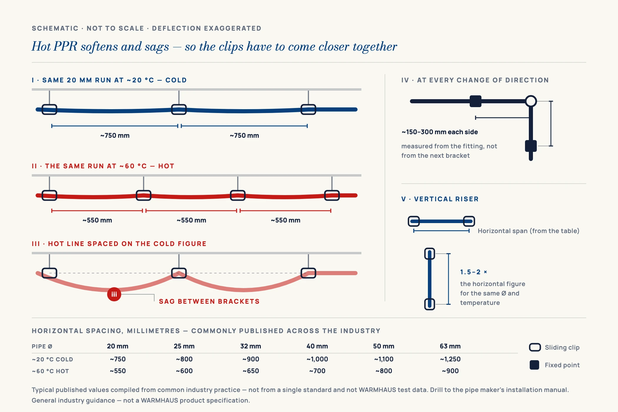
Polypropylene random copolymer is a semi-crystalline thermoplastic, and its stiffness — the modulus resisting bending under the weight of the pipe and its contents — is temperature dependent. At 20 °C a horizontal PPR run is comfortably rigid over a reasonable span. Fill it with water at 60 °C or 70 °C and the material softens measurably, so the same span now deflects visibly between brackets. That is why every credible PPR support table is indexed on two variables: outside diameter and operating temperature.
A support table with only one column has already got it wrong. Spacing for PPR is a function of diameter and water temperature together.
There is a second consequence. Because the pipe is flexible, the bracket does more than carry weight — it defines the geometry of the run. On a metal line the pipe holds its own line between widely spaced hangers; on PPR the brackets are the line. Skimp on them and the run reads as wavy from day one — cosmetic on an exposed riser, but a real hydraulic problem on a long horizontal run where a sag becomes a low point that traps sediment or air.
Vertical runs are the easy case: gravity acts along the pipe axis rather than across it, so a riser can be supported at wider intervals — as general guidance, one and a half to two times the horizontal spacing for the same diameter and temperature, subject to the datasheet. Because that relationship is a multiple rather than an independent set of values, this guide gives the horizontal figures and the multiplier rather than a second table of riser numbers. What a riser still needs is a fixed point at least once per floor, so the weight of the column goes into the structure and not into a fitting.
II. PPR Pipe Support Spacing Chart (by Diameter and Water Temperature)
The table below gives typical maximum spacing between supports for horizontal PPR runs, in millimetres, at two reference water temperatures. Read your outside diameter down the left, then across to the temperature the line will actually operate at — not the temperature it is nominally rated for. These are general industry guidance values for pipe carrying water, with no concentrated loads hanging between brackets. This page carries the support-spacing figures for this whole site; other guides link here rather than restate them, so you are working from one set of numbers instead of three. Be clear about what that set is: these are typical published values compiled from common industry practice — they are not taken from a single standard, and they are not WARMHAUS test results. Bracket spacing is set by the pipe manufacturer’s own installation manual for the exact grade, wall thickness and operating temperature you are installing, and that manual governs. Use the table to plan and to sanity-check a quotation; use the manual to drill holes.
| Pipe Ø (mm) | Cold water ~20 °C | Hot water ~60 °C |
|---|---|---|
| 20 mm | ~750 mm | ~550 mm |
| 25 mm | ~800 mm | ~600 mm |
| 32 mm | ~900 mm | ~650 mm |
| 40 mm | ~1,000 mm | ~700 mm |
| 50 mm | ~1,100 mm | ~800 mm |
| 63 mm | ~1,250 mm | ~900 mm |
Values are general industry guidance, not a WARMHAUS-specific specification. Close the spacing where a valve, meter or heavy fitting sits in the run, where the pipe is fibre-free and thin-walled, and on any line that will run continuously at the top of its temperature range. Intermediate temperatures sit between the two columns; where a line runs warm rather than fully hot, design on the hot column rather than interpolating. When in doubt, follow the printed datasheet supplied with the pipe.
Vertical risers are not given as a separate column on purpose. Riser spacing is normally expressed as a multiple of the horizontal figure for the same diameter — commonly 1.5 to 2 times — rather than as an independent set of absolute values, because the governing effect is simply that gravity acts along the pipe axis instead of across it. Take the horizontal figure for your diameter and temperature, apply the multiple, and check the result against the datasheet. A riser also needs a fixed point at least once per floor so the weight of the column goes into the structure rather than into a fitting.
Three practical rules go with the table. Place a support close to every change of direction, so thermal movement is transferred into the leg you intend rather than into the fitting; as general guidance that means a fixing within roughly 150–300 mm of an elbow or tee, though the figure that governs is whatever the pipe manufacturer’s installation instructions state. Support heavy components independently: a brass ball valve, a strainer or a meter must not hang off the pipe between two brackets. And treat these figures as maxima, not targets — nobody has ever been called back to site because the clips were too close together.
III. Fixed Points vs Sliding Clips — the Distinction That Matters
Every PPR support falls into one of two categories, and confusing them is the most common design error on thermoplastic pipework. A fixed point clamps the pipe so it cannot move axially; it anchors the run and defines where expansion is forced to go. Fixed points normally sit close to branch tees, at the base and head of risers, and at either end of a section containing an expansion feature. A sliding clip — sometimes called a guide — holds the pipe in line and carries its weight but lets it slide freely along its own axis. The vast majority of clips on a job should be sliding.
The correct pattern is simple: a section of pipe is anchored at fixed points, guided by sliding clips in between, and given one place to absorb the movement. Make every clip a fixed point and the pipe has nowhere to grow, so thermal load goes into the material and the joints as compressive stress — that is what buckles a run into an S-shape. Make every clip sliding with no anchor at all and the run wanders, with movement accumulating at whichever fitting is stiffest.
IV. Thermal Expansion — How Much, and Where It Goes
Plain PPR expands in the order of 0.15 mm per metre per °C, and fibre-reinforced (composite / faser) pipe considerably less — commonly quoted somewhere in the region of 0.03–0.06 mm per metre per °C — which is precisely why the reinforced grades exist for hot lines. That reinforced figure is a range rather than a single value because it depends heavily on how the fibre layer is constructed and what proportion of the wall it occupies, and those differ between grades and manufacturers; treat it as an order of magnitude and take the actual coefficient from the datasheet. Multiply the run length by the temperature rise between cold-fill and full operating temperature and you get the movement you have to design for.
A worked example: a 10 metre plain PPR hot run installed at 20 °C and operated at 70 °C sees a 50 °C rise. At 0.15 mm/m/°C that is 10 × 50 × 0.15 = 75 mm of length change — a visible amount of movement that has to go somewhere deliberate. The same run in a fibre-reinforced grade moves a fraction of that, but how small a fraction depends on the specific construction, so run the arithmetic with the coefficient printed for the grade you are buying rather than with a generic figure. Thermal movement is treated at length in our guide to PPR pipe thermal expansion.
There are several standard ways to absorb that movement, and all of them depend on the clips being set out correctly:
Expansion loop (U-bend)
A U-shaped detour whose legs flex sideways as the pipe grows. The loop must sit between two fixed points, with sliding clips only on the legs — a fixed clip on a loop leg defeats the feature.
Expansion arm (L-leg)
Where the run already changes direction, the perpendicular leg does the work. It must be long enough to flex, which means no fixed point close to the corner on the flexing side — commonly missed when both legs of an elbow get anchored “to be safe”.
Free movement in a chase or duct
Where the pipe is concealed, insulation or a conduit sleeve gives it room to move. Never mortar a hot PPR line in rigidly along its whole length and expect an expansion feature elsewhere to save it.
The required loop or leg length scales with the pipe diameter and the calculated movement. Manufacturers publish leg-length formulas per grade; use the one supplied with your pipe rather than a generic number.
V. Choosing the Clip Itself
The clip has to match three things: the pipe’s outside diameter, the line temperature, and the fixing substrate.
On diameter, a PPR clip is sized to the pipe OD, not to a nominal bore — a 25 mm PPR pipe takes a 25 mm clip. Using a clip intended for a different material with the same nominal size is where “the clip won’t close” and “the pipe rattles in the clip” both come from, and a rattling pipe is a guide that has become a noise source.
On temperature, plastic clips are adequate for cold and moderate warm lines but should be checked against the continuous operating temperature of a hot run; rubber-lined metal saddle clips are the usual answer on hot lines and where noise transmission into the structure is a concern. The liner also stops the pipe being point-loaded by a hard metal edge.
On substrate, the fixing is only as good as what it goes into — plasterboard needs a cavity fixing or a noggin, lightweight block needs the right anchor, and a well-specified clip in crumbling render fails like an undersized one. This is also where pipe and fittings from one manufacturer pay off: outside diameters stay consistent, so one clip size works end to end.
VI. Common Clip and Spacing Mistakes
These faults turn up repeatedly when a PPR installation is inspected after its first heating season — all avoidable at the design stage.
Metal-pipe spacing copied onto PPR
Steel and copper tables allow far wider spans; applied to PPR they produce immediate sag. Fix: use a PPR-specific table indexed on diameter and temperature.
Spacing chosen for cold, line runs hot
The same pipe needs closer supports at 60 °C than at 20 °C. Fix: space on the hot column whenever a line is dual-use.
Every clip made a fixed point
The run cannot grow, so it buckles or loads its fittings in compression. Fix: anchor deliberately at defined fixed points; everything between them slides.
Clip overtightened onto the pipe
A sliding clip clamped hard becomes an accidental fixed point and can score or deform the pipe wall. Fix: sliding clips should hold the pipe firmly in line but let it move axially by hand.
No support near elbows, tees and valves
Movement and weight go into the fitting instead of the bracket. Fix: support close to every direction change, and carry valves and meters on their own brackets.
Expansion loop clamped rigidly
A fixed clip on a loop leg cancels the feature; the pipe is now anchored at both ends with nothing to flex. Fix: guides only within the loop, fixed points outside it.
Clip fixed before the joint has cooled
Clamping a freshly welded run pulls the joint out of alignment as it sets. Fix: finish the hot-melt welding and cooling sequence first, then clip.
VII. One Source for Pipe, Fittings and the Rest of the System
Support spacing is only reliable when the pipe you are clipping is dimensionally consistent from batch to batch — a bracket set out for one outside diameter does not forgive drift. WARMHAUS is a manufacturer of PPR, PEX and brass piping systems, not a trading company. The extrusion, injection-moulding and machining lines are our own, which is why pipe tolerances and PPR fitting socket dimensions are held to one internal standard rather than averaged across several suppliers. Manufacturing since 1993, ISO 9001 / ISO 14001 / ISO 45001 certified, EU CE marked and SGS tested; raw material from Hyosung, Borealis and LG.
For a distributor or contractor that means a single account for the complete PPR system — pipe, fittings and valves — alongside PEX, brass and underfloor-heating lines across our full product range, so a mixed container does not need three supplier relationships. No MOQ, standard lead time 45 days, certificate documents available on request. Request the PPR system specification sheet and distributor terms .