A PPR riser that snakes across a ceiling in a wave, a bracket torn out of a wall, a hot-water branch that ticks every time the boiler fires — these are not material failures. They are thermal expansion that was never given anywhere to go. Polypropylene expands roughly an order of magnitude more than copper, which stops being academic around the first ten metres. The fix is not stronger pipe or more clamps but the opposite: fewer fixed points, more sliding supports, and somewhere to move.
A specifier needs the numbers at layout stage — you cannot retrofit a loop into a closed wall. An installer needs the bracket rules, because most field damage comes from a run clamped rigidly at both ends with good intentions. Everything below is general industry guidance for PPR (PP-R type 3); always confirm against the datasheet of the pipe you are installing.
I. Why PPR Moves So Much More Than Metal
Every material has a coefficient of linear thermal expansion — how much one metre grows per degree of temperature rise. For plain PP-R the figure commonly used is around 0.15 mm per metre per °C; copper sits near 0.017 and steel near 0.012. So PPR moves roughly eight to twelve times as far as metal — not a defect but normal thermoplastic behaviour, the price of a material that does not corrode.
The pipe is not too weak to resist expansion. Nothing is. The question is never whether it moves — only whether you decided where.
A second figure changes the arithmetic. Fibre-reinforced (composite) PPR carries a middle layer restraining movement along the pipe axis, and its coefficient is commonly quoted at roughly 0.03–0.05 mm/m/°C — between about a fifth and a third of plain PP-R. That is why composite is the default for long hot-water risers: it shrinks the problem to something a normal bracket layout handles. The wall constructions are set out in our guide to the PPR pipe range.
One distinction causes arguments on site: expansion depends on the change in temperature, not the absolute temperature. A pipe installed at 35 °C carrying 70 °C water sees a 35 °C rise; the same pipe installed at 5 °C sees 65 °C — nearly double the movement from the same design. Installation temperature is part of the calculation, and the part most often forgotten.
II. PPR Expansion Table — Movement by Run Length and Temperature Rise
The formula is simple enough to do on a ladder: ΔL = α × L × ΔT — change in length (mm) equals the coefficient (mm/m/°C) times run length (m) times the temperature difference (°C) between installation and operation. The table applies α = 0.15 mm/m/°C, plain PP-R and the worst case, so the figures are a conservative design ceiling.
| Run length | ΔT 20 °C | ΔT 30 °C | ΔT 40 °C | ΔT 50 °C | ΔT 60 °C |
|---|---|---|---|---|---|
| 1 m | 3 mm | 4.5 mm | 6 mm | 7.5 mm | 9 mm |
| 2 m | 6 mm | 9 mm | 12 mm | 15 mm | 18 mm |
| 5 m | 15 mm | 22.5 mm | 30 mm | 37.5 mm | 45 mm |
| 10 m | 30 mm | 45 mm | 60 mm | 75 mm | 90 mm |
| 15 m | 45 mm | 67.5 mm | 90 mm | 112.5 mm | 135 mm |
| 20 m | 60 mm | 90 mm | 120 mm | 150 mm | 180 mm |
Values are general industry guidance based on α ≈ 0.15 mm/m/°C for plain PP-R, not a WARMHAUS-specific specification. Composite PPR moves substantially less — commonly around 0.03–0.05 mm/m/°C — so divide accordingly. Always confirm the coefficient on the datasheet of the pipe you are installing.
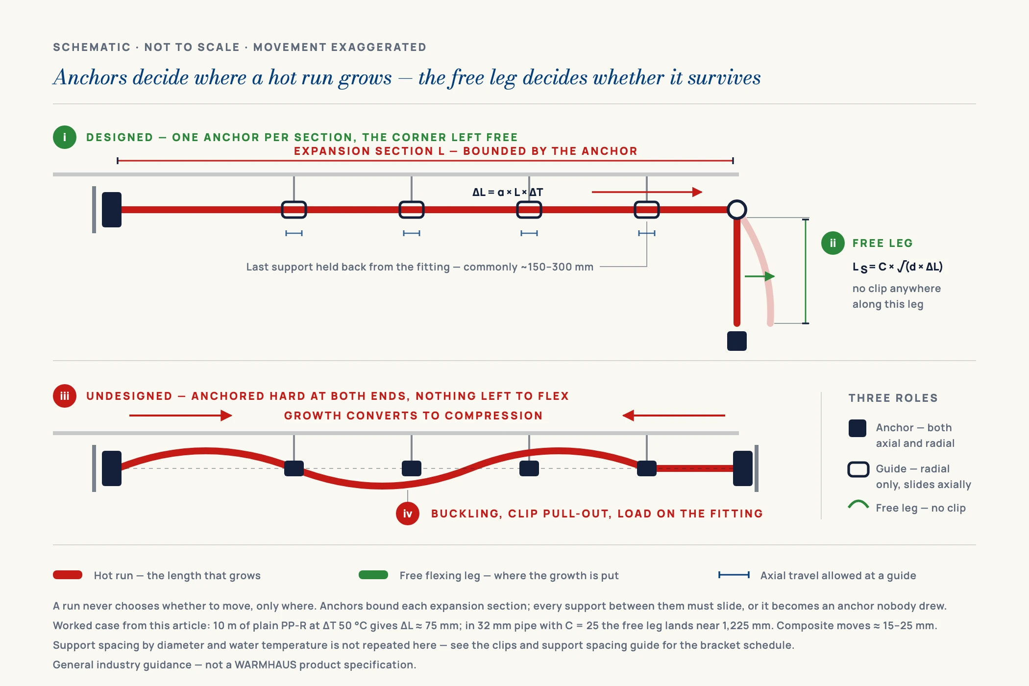
One row makes the consequence obvious. A 10 m hot-water run with a 50 °C rise moves 75 mm — the width of a hand. No bracket absorbs that by brute force. Fix both ends rigidly and the movement becomes compressive stress in the pipe wall: the run buckles, a clamp pulls out, or the load concentrates at a fitting. Composite pipe yields roughly 15–25 mm on the same run — within range for a well-placed loop.
III. The Three Ways to Absorb Movement
Once you know how far the run travels, absorbing it is geometry. All three methods convert axial movement into gentle bending in a leg of pipe free to flex, and all depend on one rule: the flexing leg must be unrestrained. A perfectly sized loop with a clamp in the middle is not a loop.
I. Expansion loops (U-bends)
A loop is a U-shaped detour of four elbows, placed midway between two fixed points. As the straight sections grow, the legs of the U flex outward and take up the movement. Loops are the standard answer for long straight runs — risers, plant-room mains, exposed distribution. The loop needs clear space and sliding supports on the approaches, never a rigid clamp on the loop itself.
II. Expansion arms and offsets (Z-bends)
Where a run already changes direction, that corner is a free expansion arm — leave it long enough and unclamped, keeping the fixed point back from the corner so the perpendicular leg can flex. It is the cheapest method, using geometry the layout already contains, and the one most often destroyed by an installer who clamps tight to the elbow because it looked untidy.
III. Bellows and sleeved compensators
Where there is genuinely no room — a service shaft, a tight ceiling void — a purpose-made axial compensator absorbs movement in a fixed footprint. It costs more and adds a component to maintain, so it belongs where space, not budget, is the binding constraint.
Sizing the flexing leg — the formula behind all three
Leg length is a calculation, not a guess. The form used across thermoplastic pipework is LS = C × √(d × ΔL), where LS is the required free leg length in mm, d is the outside diameter in mm, ΔL the calculated movement in mm from the table above, and C a material constant. For polypropylene, C is commonly taken as about 20–30; use the higher end when you want margin, and always prefer the constant printed in the pipe manufacturer’s design data over a generic one.
Worked example, so the formula is usable rather than decorative. Take the row highlighted above: a 10 m plain PP-R run with a 50 °C rise, ΔL = 75 mm, in 32 mm pipe. Then √(32 × 75) = √2,400 ≈ 49, and with C = 25 the free leg comes out at LS ≈ 1,225 mm — roughly 1.2 m of unrestrained pipe perpendicular to the run. For an expansion loop (a U of four elbows) that leg is each side of the U, and the width across the loop is usually taken at about half the leg length, so this example needs a U roughly 1.2 m deep and 0.6 m wide. That is a real amount of ceiling void, which is precisely why the number belongs on the drawing at layout stage rather than in the installer’s head on site.
Two consequences follow directly. Bigger pipe needs a longer leg — repeat the same sum at 63 mm and LS rises to about 1,720 mm, so a 63 mm main cannot use the tight offset that works on a 20 mm branch. And because the diameter sits under a square root, halving the movement is worth more than halving the diameter: switching that run to fibre-composite pipe drops ΔL from 75 mm to roughly 15–25 mm and the required leg to around 550–700 mm. These constants are general industry guidance, not a WARMHAUS specification — confirm C and the loop geometry against the design table supplied with the pipe.
IV. Fixed Points and Sliding Supports — Where Installers Go Wrong
Bracketing is where good design gets undone. The principle is short: a fixed point tells the pipe which direction to grow; every other support only carries weight and keeps the line straight. A run with fixed points every two metres is fighting itself along its whole length.
Clamping the whole run rigidly
Every bracket tightened hard, because it feels like better workmanship. The run has no free length to flex, so stress goes into the pipe wall and fixings. Fix: one fixed point per section, sliding supports everywhere else.
Fixing hard against a corner
A clamp at the elbow removes the free expansion arm the layout gave you, driving movement into the fitting. Fix: hold the fixed point back from the change of direction and leave the perpendicular leg unrestrained.
Over-tight sliding clips
A sliding support that grips is a fixed point nobody drew — the usual cause of a wavy ceiling run that “was installed exactly as specified”. Fix: clips should locate the pipe, not pinch it; check it can be pushed through by hand.
No clearance at wall and slab penetrations
Pipe mortared solidly into a wall becomes an unintended fixed point, and the movement is taken at the collar. Fix: sleeve every penetration and leave an annular gap; use a flexible sealant, not rigid mortar, against the pipe.
Choosing plain pipe for a long exposed hot run
Plain PP-R on a 20 m exposed riser generates movement no bracket layout absorbs gracefully. Fix: specify composite for long hot-water and exposed runs, and keep plain pipe for short branches and cold services.
Blaming the joint
A leak at a fitting on a rigidly clamped run is a symptom, not a cause — the fitting was where the stress landed. Fix: check the bracket layout before rewelding; correctly welded PPR fittings fail mainly when the run is loading them.
V. Support Spacing — and Two Details That Change It
Support spacing and expansion are separate problems sharing the same brackets: spacing stops the pipe sagging, expansion decides which brackets may grip. Two rules govern the spacing side — hot lines need closer spacing than cold, because polypropylene loses stiffness as it warms, and vertical runs tolerate wider spacing, roughly one and a half to two times the horizontal figure, because gravity acts along the pipe rather than across it. Near a change of direction, place a fixed support within roughly 150–300 mm of the elbow or tee so movement is driven into the leg you intended.
We deliberately do not repeat the spacing table here. The full figures by diameter and water temperature live in one place on this site — our guide to PPR pipe clips and support spacing — so that a specifier comparing two of our pages never finds two different numbers for the same pipe. Use that table for the bracket schedule and this page for the movement calculation.
Two details belong on the drawing. Pipe buried in screed or chased into plaster is restrained along its length and the surrounding material shares the load — free expansion is largely a problem of visible pipework. And insulation helps twice: it reduces the temperature swing, and inside a sleeve it gives the clearance that lets the pipe move at penetrations.
VI. One System, Matched Tolerances — What WARMHAUS Supplies
Expansion is a system property, not a pipe property. It shows up at the brackets, at the fittings, and where plain pipe changes to composite along a riser — exactly where a project buying pipe and fittings from different sources sees mismatch. WARMHAUS is a manufacturer of PPR, PEX and brass piping systems, not a trading company. The extrusion, injection-moulding and machining lines are our own, so both constructions in the same PPR system match one fitting range.
Manufacturing since 1993, ISO 9001 / ISO 14001 / ISO 45001 certified, EU CE marked and SGS tested. Separately from those certifications — which cover our management systems and market access, not pipe geometry — the dimensional and quality requirements we produce PPR pipe to are those of DIN 8077 / DIN 8078. There is no MOQ: a distributor can take a working quantity of composite pipe for risers alongside plain pipe for branch work without committing to a container of each. Standard lead time is 45 days on planned production slots.
Tell us the project’s run lengths, operating temperatures and diameters and we will send the matching pipe and fitting specifications and distributor terms. Request the PPR system specifications and expansion design data — pricing, certification files and exact certificate documents available on request.