There is no single correct underfloor heating flow temperature. There is only the lowest temperature that still delivers the room’s heat loss through the floor build-up you actually have — and on most screed floors with tile or stone finish, that lands somewhere in the 35–45 °C band, not the 55–70 °C a boiler leaves at. Setting it is a calculation with four inputs: floor covering resistance, pipe spacing, screed depth and room heat loss. Set it too low and rooms never reach setpoint on the coldest day. Set it too high and you overshoot the floor surface temperature limit, cook timber finishes, and throw away the efficiency that made radiant heating worth specifying.
Everything below is general industry guidance, not a WARMHAUS-specific specification — floor constructions, emitter outputs and control equipment vary, so always confirm the final figures against the datasheets of the pipe, the mixing group and the floor covering you are using, together with the project heat-loss calculation.
I. Why the Manifold Runs Cooler Than the Boiler
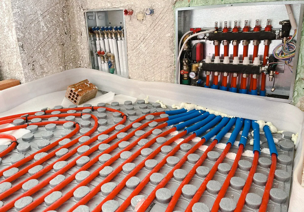
A radiator is a small, hot emitter. An underfloor circuit is an enormous, cool one. The entire floor slab is the heat exchanger, so the same kilowatts come out of a much larger surface at a much lower temperature difference. That is the whole physical basis of the system, and it is why a heat source running at boiler flow temperature cannot be connected straight to the loops. Something has to sit between them and blend the hot supply with returning loop water — that is the job of the mixing group, and our guide to underfloor heating manifold installation covers where it sits in the assembly.
The consequence is commercial, not just technical. Condensing boilers only condense when return temperatures stay low, and heat pumps lose coefficient of performance sharply as flow temperature climbs. Every degree taken off the manifold without losing comfort is efficiency kept — which is why low-temperature operation is the headline argument for underfloor heating systems, and why over-setting the mixing valve quietly undoes the reason the client paid for one.
The correct flow temperature is the lowest one that still meets heat loss on the design day — not the one that heats the room fastest.
II. The Four Inputs That Decide the Number
Before touching the mixing valve, you need four figures. Three come from the floor construction and one from the building.
Floor covering thermal resistance
The single biggest variable. Tile and stone are close to thermally transparent; carpet, thick underlay and engineered timber are insulation sitting on top of the emitter. A high-resistance covering forces the flow temperature up to push the same output through — which is why the covering must be decided before the system is designed, not after the screed has gone down.
Pipe spacing (loop centres)
Tighter centres put more heated pipe under each square metre, so the floor delivers the same output at a lower water temperature and with a more even surface. Widening centres to save pipe is a false economy that gets paid back as a permanently higher flow temperature and visible striping on the floor.
Screed type and cover depth over the pipe
Screed depth governs both heat spread and response time. A thicker traditional screed diffuses heat laterally and evens out surface temperature, but reacts slowly; a thin liquid or low-profile build-up responds faster and generally suits a slightly different setting and control strategy.
Room heat loss per square metre
The demand side. A well-insulated room asking for a modest output per square metre can be served at the bottom of the range; a room with large glazing, high ceilings or poor fabric may exceed what the floor can deliver at any acceptable temperature, and needs supplementary emitters rather than a hotter manifold.
And one hard limit above all four
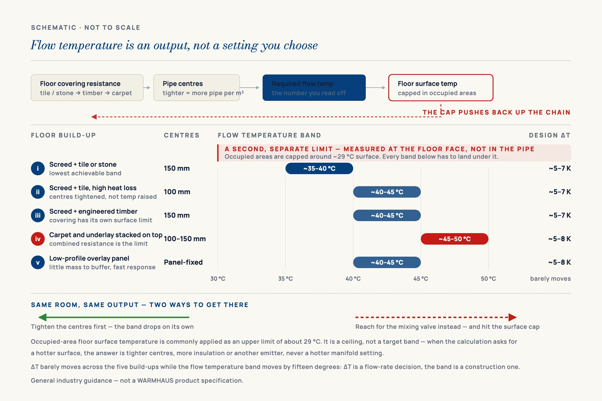
Floor surface temperature, as set out in the EN 1264 / ISO 11855 family for embedded surface heating — commonly applied as about 29 °C in occupied areas, about 35 °C in perimeter strips and about 33 °C in bathrooms. That caps the surface and therefore caps the flow temperature no matter what the heat-loss figure says. If the calculation demands a surface hotter than the limit, the answer is more insulation or an additional emitter — never a hotter setting.
III. Flow Temperature Table by Floor Build-Up
The table below gives typical flow temperature bands for common floor constructions, together with the differential across flow and return that each is usually designed around. Read it as a starting band for commissioning, then verify against the project heat-loss calculation — two rooms with the same floor build-up and different fabric performance will not settle at the same number.
| Floor build-up | Typical pipe centres | Typical flow temp | Flow–return ΔT | Notes |
|---|---|---|---|---|
| Screed + tile or stone | 150 mm | ~35–40 °C | ~5–7 K | Lowest achievable band; ideal for heat pumps |
| Screed + tile, high heat loss | 100 mm | ~40–45 °C | ~5–7 K | Tighten centres before raising temperature |
| Screed + engineered timber | 150 mm | ~40–45 °C | ~5–7 K | Confirm the covering’s own maximum surface limit |
| Screed + carpet and underlay | 100–150 mm | ~45–50 °C | ~5–8 K | Combined covering resistance is the limiting factor |
| Low-profile / overlay panel | Panel-fixed | ~40–45 °C | ~5–8 K | Fast response, less thermal mass to buffer |
| Suspended timber, joist void | 200 mm | ~45–55 °C | ~5–8 K | Poor emission is offset by flow temperature, not by a wider ΔT — spreader plates and insulation beneath are what make the band achievable |
| Perimeter / edge zone strip | 100 mm | As room band | As room | Tighter centres at glazing, not a higher temperature |
Values are general industry guidance, not a WARMHAUS-specific specification. Actual settings depend on the project heat-loss calculation, the covering manufacturer’s stated resistance and surface limit, insulation below the loops, and the control strategy in use. Always confirm against the datasheets of the pipe, mixing group and floor covering actually installed.
Note that the ΔT column barely moves while the flow temperature column moves by twenty degrees. That is deliberate, and it is the part of the table most often got wrong. Design ΔT is a flow rate decision, not a floor-construction decision: for a given output, flow rate and ΔT are inversely related, so widening ΔT means supplying the loop with less water. A build-up with poor heat transfer — a joist void with spreader plates is the worst common case — needs at least as much flow as a screed floor, not less, so it is compensated with a higher flow temperature at a similar ΔT. Widening ΔT there would starve the circuit and leave the far end of the loop cold, which is the same fault the balancing section treats as a defect. Keep ΔT inside the design band and let flow temperature do the work.
IV. Surface Temperature — The Limit That Caps Everything
Flow temperature is the input; floor surface temperature is what the occupant and the floor covering actually experience, and it is where the ceiling sits. The limits are not folklore — they come from the public standard family for water-based embedded surface heating and cooling: EN 1264 in Europe and its international counterpart ISO 11855, which set out the design method, the surface temperature limits and the output testing basis. The figures those documents are commonly applied with are shown below.
| Floor area | Commonly applied surface limit | Why the limit is where it is |
|---|---|---|
| Occupied living areas | ~29 °C | Foot comfort for people standing or walking for long periods in normal footwear |
| Perimeter / edge zones | ~35 °C | A narrow strip near glazing and external walls, occupied only in passing, so a higher surface is tolerated to offset the local heat loss |
| Bathrooms and wet areas | ~33 °C | Occupants are barefoot and often wet, and the room setpoint itself is higher |
Surface temperature limits are general industry guidance drawn from the EN 1264 / ISO 11855 standard family for embedded surface heating, not a WARMHAUS specification, and the exact figures and their national application differ by edition and by market. The binding number on any job is whichever is lower: the design standard applied to the project, or the floor covering manufacturer’s own stated maximum — which is usually the tighter constraint. Always confirm against the current standard applied on the project and the covering datasheet.
Two consequences follow for the manifold. First, the perimeter allowance is a strip, not a room setting: it is achieved with tighter pipe centres in that band, fed from the same loop temperature, not by supplying part of the floor hotter. Second, a surface limit is what makes the calculation terminate. If the heat-loss figure demands a surface above the limit, no mixing valve setting solves it — the fix is fabric, insulation or a supplementary emitter.
The pipe has a temperature class, and underfloor heating has its own
There is a second limit that specifiers meet at the ordering stage rather than at the mixing valve: the application class the pipe is rated to. ISO 10508 classifies plastic piping for hot and cold water in buildings by service condition, and each class is a defined lifetime profile — a combination of design temperature, years at that temperature, a period at a higher operating temperature and a short malfunction temperature — not a single number. The class most relevant here is the one written for radiant floors.
| Class | Typical application | Design temperature basis |
|---|---|---|
| Class 1 | Hot water supply at the lower service condition | ~60 °C |
| Class 2 | Hot water supply at the higher service condition | ~70 °C |
| Class 4 | Underfloor heating and low-temperature radiators | Lower-temperature profile combining ~20 °C, ~40 °C and ~60 °C periods |
| Class 5 | Higher-temperature radiator systems | Profile extending to ~80 °C |
Class descriptions are general industry guidance summarising how ISO 10508 application classes are commonly used, not a WARMHAUS specification and not a reproduction of the standard. Each class is defined as a full time-at-temperature profile over a design life, together with a design pressure; the summary above is orientation only. Confirm the class, the design pressure and the design life stated on the datasheet of the pipe you are actually installing.
The practical point for commissioning: Class 4 is the underfloor heating class, and it is written around the low flow temperatures this article argues for. A floor build-up that forces you to the top of the flow temperature table is not only expensive to run — it is eating into the margin the pipe’s class profile assumed. Our guide to PEX pipe for underfloor heating covers how the class and the pressure rating are read together on a datasheet.
Timber and resilient coverings punish a hot setting hardest. Exceeding a timber manufacturer’s stated surface limit risks shrinkage, gapping and warranty refusal, and the failure appears months after handover when nobody connects it to the mixing valve. Where a client changes their floor finish late, revisit the flow temperature rather than assuming the original commissioning still stands.
V. Setting the Temperature at the Manifold, in Order
Sequence matters. Setting flow temperature before the loops are balanced means you are tuning against a moving target, because unbalanced loops change return temperature and therefore the blend. The order below assumes the system is already filled, vented and pressure tested.
I. Balance the loops first
Set loop flow rates on the flow meters to the design figures before touching the mixing valve. A manifold with wildly different loop lengths all running wide open will starve the long circuits regardless of what temperature you supply. Our radiant floor heating guide covers how loop layout and flow rates are set before commissioning begins.
II. Set the mixing valve to the calculated band
Start at the design flow temperature from the heat-loss calculation, or at the lower end of the relevant band in the table above. Starting low and working up is the disciplined approach — starting high and working down means the building has already been overheated and the thermal mass will mask the result for hours.
III. Let the slab reach steady state before judging
A screed floor is a large thermal store and does not respond in minutes. Give the system time at a fixed setting before adjusting again — reading a slab mid-transient and changing the valve is how installers end up chasing a system in circles across a whole commissioning day.
IV. Verify flow and return, not just the dial
Check actual flow and return temperatures at the manifold bars and compare the differential with the design figure — the one on the commissioning sheet, not a generic number. A ΔT far below design usually means over-pumping or a mixing valve blending more than intended; a ΔT far above design points to insufficient flow or an undersized circulator, and it is the same reading whatever the floor build-up. Do not talk yourself into accepting a wide ΔT because the floor is a difficult one: a joist void does not justify less flow, it justifies a higher supply temperature at the same differential.
V. Record the setting on the commissioning sheet
Write down the final flow temperature, the differential and the loop flow rates. Without a record, the next person to touch the system has no reference point, and a well-commissioned manifold drifts back to guesswork within one heating season.
VI. Fixed, Weather-Compensated and Room-Influenced Control
A single fixed flow temperature has to be set for the design day — the coldest condition the system must cover. For most of the heating season, that setting is higher than the building needs, and the controls compensate by cycling zones on and off. It works, and on small residential jobs it is often the sensible specification.
Weather compensation moves the flow temperature itself against outdoor temperature, so the manifold supplies genuinely cooler water in mild weather instead of hotter water intermittently. On heat-pump systems this is close to a requirement, because the efficiency penalty of running at design flow temperature all season is substantial. Room-influenced compensation adds a feedback signal from a reference space, trimming the curve when internal gains — solar, occupancy, cooking — mean the outdoor sensor alone overstates demand.
Whichever strategy is specified, the manifold hardware has to support it: the actuator heads, the thermostats and the wiring centre all have to speak to the same control logic. That is a specification decision worth making early, and our underfloor heating controls range — thermostats, actuators and wiring centres — is designed to be selected alongside the manifold rather than sourced separately afterwards.
VII. Five Symptoms That Trace Back to Flow Temperature
When a radiant system underperforms, the mixing valve setting is one of the first things to check — but the symptom tells you which direction to look.
Rooms never reach setpoint on the coldest days
Either the setting is below the design figure, or the floor cannot deliver the room’s heat loss at any acceptable temperature. Check heat loss against the floor’s output before raising the setting — if the floor is undersized, a hotter manifold will not fix it and will breach the surface limit trying.
Floor feels uncomfortably warm underfoot
Surface temperature is above the comfort limit, which almost always means the mixing valve is set too high — often raised to compensate for unbalanced loops or a high-resistance covering added after design. Rebalance first, then reduce the setting.
Visible striping across the floor surface
Warm bands over the pipe runs and cool bands between them. The cause is wide pipe centres combined with a high flow temperature and insufficient screed cover to diffuse the heat laterally. Lower the flow temperature if output allows; the real fix is at design stage in the spacing.
Timber flooring gaps or cups after a season
A strong indicator that the covering’s stated maximum surface temperature has been exceeded, frequently after a late change of floor finish that nobody fed back to the commissioning setting. Reset to the covering manufacturer’s limit and record it.
Boiler short-cycles or heat pump efficiency drops
Return temperature is too high for the heat source to work in its efficient range. Check the flow–return differential against design; an over-pumped, over-hot circuit returns water nearly as hot as it left, which is exactly what a condensing boiler or heat pump cannot use.
VIII. Hardware That Makes the Setting Hold
A flow temperature setting is only as reliable as the components holding it. Reaching a number on commissioning day is straightforward; holding it through five heating seasons depends on the manifold bar, the mixing group and the loop pipe being dimensioned to one standard rather than assembled from three suppliers with three tolerance regimes. WARMHAUS is a manufacturer of PPR, PEX and brass piping systems — not a trading company. The extrusion, injection-moulding and machining lines are our own, so the brass manifolds, the loop pipe and the controls that act on them are specified against each other before they reach a project.
That matters at the ordering stage too. Manifold bars, actuator heads, thermostats, wiring centres and PEX loop pipe come from one source with one set of certification files — ISO 9001, ISO 14001 and ISO 45001 certified, EU CE marked and SGS tested, manufacturing since 1993. There is no MOQ, so a first order can be a mixed pallet covering a single project rather than a container of one line item; standard lead time is 45 days on planned production slots.
Request the underfloor heating manifold and controls specifications — tell us the outlet counts, the control strategy and the markets you serve, and we will send the manifold range, the controls range and distributor terms. Certificate documents, pricing and detailed parameters: available on request.