Zoned UFH and a Heat Pump: What Must Remain Available?
Before finalising closable UFH zones, obtain source-side flow evidence for the relevant valve states and a separate available-water-volume assessment against the exact heat-source instructions. Keep those decisions distinct from loop count, room demand and component matching.
Key Takeaways
- Map every valve that can close in the relevant operating states.
- Identify source-side evidence separately from floor-loop balancing.
- Check flow rate and available water volume independently.
- Keep named-model requirements attached to their manual revision.
- A missing or below-criterion record means a defined review hold.
- Confirm the manifold/control interface without inventing a heat-source design.
Start with the state in which the zones can close
A manifold schedule has eight loops, the rooms reach their setpoints, and the actuators can close. The buying question is no longer just whether the port count is right. Which water path and water volume remain available to the heat source in the operating states its manufacturer requires? Put that question on the interface sheet before accepting the control package.
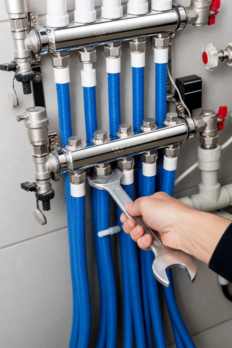
This is a document review for the responsible designer, installer and component supplier. It is not an instruction to operate a pump test, change a bypass, remove an actuator or alter wiring. A distributor can collect and reconcile the necessary evidence without deciding the hydraulic remedy. A photograph of open flow meters, by itself, cannot close the source-side question.
The practical concern appears in a real historical discussion: a BuildHub question dated 21 February 2023 asks about closing larger UFH areas while an individual room still heats and about the resulting buffer decision. That is a homeowner question, not a WARMHAUS enquiry or proof of current search volume. The professional interface check developed here is an inference from that concern and the named manufacturer documentation.
Begin the sheet with the exact heat-source model, applicable manual revision and drawing reference. Add the manifold identifier, each controlled loop and which valves can close. Distinguish a room thermostat being satisfied from a valve actually having reached its closed position. Where those details are not established, record them as missing rather than assuming a permanent open path.
Identify what the measurement actually represents
A loop flow meter helps describe flow in that loop. It does not automatically document the flow through the heat source. The distinction matters where the drawing contains a mixing group, separate pumps or hydraulic separation: circulation within the floor distribution circuit need not be identical to source-side circulation. Ask the responsible professional to identify the relevant measurement point and the path it represents.
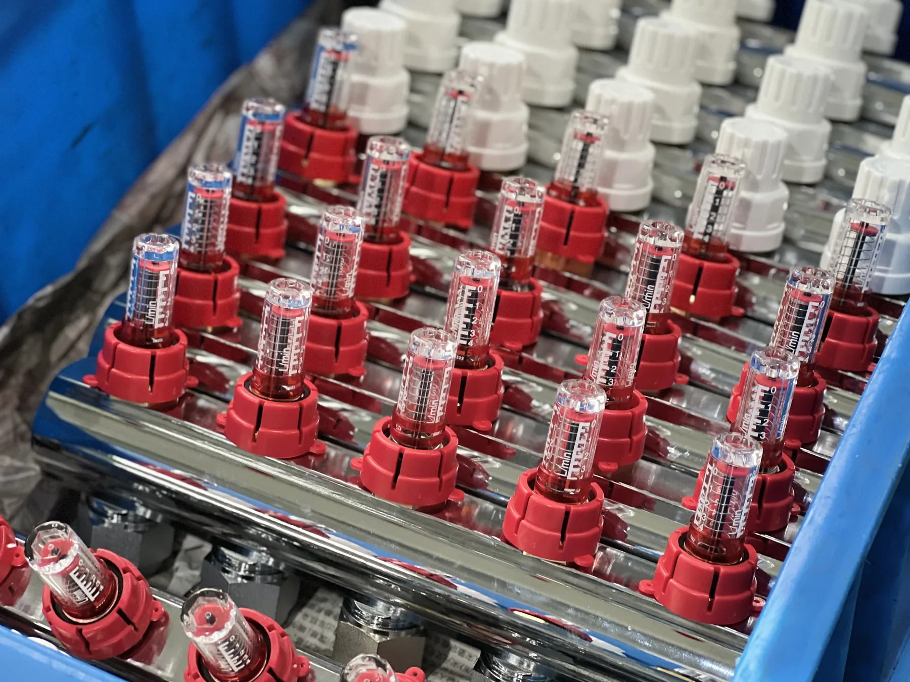
Our pump and mixing unit guide discusses return water recirculating into a mixing arrangement. Its use of the word bypass describes that arrangement; it is not evidence that the exact heat source retains its required flow when controlled loops close. Do not approve a different function merely because the same word appears on two drawings.
Keep a separate row for the normal all-open balancing record. It can remain useful evidence for the floor distribution task while being insufficient for the closed-state source check. The interface sheet should state what each reading proves, which valves were in which state and which operating condition was being assessed. A number without that context invites a false comparison.
Read flow and volume as separate model-specific requirements
The Daikin Altherma 3 H W installation manual 4P644479-1A, September 2021, for EABH/X16DF6V(7)+9W(7), provides a concrete example. Its printed page 7 distinguishes a minimum installation water volume of 20 litres, excluding the outdoor unit’s internal water volume, from a minimum flow rate of 20 litres per minute for defrost/backup-heater operation. The closed remotely controlled valve condition matters to the stated guarantees.
Those two numbers happen to begin with twenty, but their units answer different questions. Litres describe an amount of water. Litres per minute describe a rate through the relevant circuit. A flow result cannot be converted into available installation volume merely by dropping the time unit. Nor does a total water-content figure establish that the required circulation is maintained.
These are historical, named-model requirements, not general heat-pump setpoints and not WARMHAUS ratings. Confirm the exact installed unit and applicable instructions before using any numerical criterion. The same manual has additional operating guidance and a professional commissioning procedure; the two figures above are not a substitute for that procedure or for its complete conditions. This article deliberately does not reproduce setting menus or adjustment instructions.
For the volume row, ask the designer to identify the water counted, any exclusions and what remains available under the relevant valve states. A pipe-length total or an unqualified tank name is not a completed answer. The drawing and calculation must make the claimed availability intelligible to the person accepting the system.
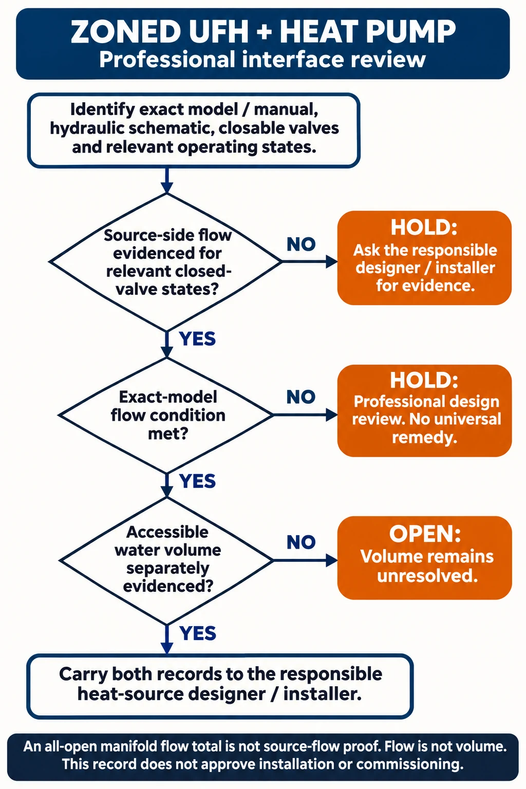
Open the interface-review map at full size.
- Identify exact heat-source model/manual, hydraulic schematic, closable valves and relevant operating states.
- If source-side flow evidence for relevant closed-valve states is missing, hold the interface review and obtain evidence from the responsible designer/installer.
- If the documented source-side flow does not meet that exact model condition, hold for professional design review; do not prescribe a universal remedy.
- If flow evidence supports that condition, separately establish accessible water volume for applicable states. Missing volume evidence leaves this question open.
- Carry both supported records to the responsible heat-source designer/installer; the record does not approve commissioning or installation.
Record A: all-open balancing does not settle the closed state
Consider a fictional interface review in which the installer supplies an all-open floor balancing sheet with a loop-flow sum of 24 L/min. The project’s source requirement and relevant closed-state method still need confirmation. The record says nothing about source-side flow after the controlled valves close. There is also a mixing arrangement on the drawing.
The completed decision is “source minimum-flow acceptance unresolved.” Retain the balancing sheet for its own purpose, but request the exact source criterion, marked measurement point and professional evidence for the required valve and operating states. Do not accept 24 L/min as a source-side result simply because the arithmetic is greater than a number found in a manual.
Change one material input: the responsible installer now supplies a source-side record, identifies the applicable manufacturer method and maps the relevant closed valves. That resolves the evidence-location gap and permits a criterion-specific review. It does not automatically establish a passing value, accessible volume or approval of every other system requirement.
Record B: a below-criterion result requires design review
In a second fictional record, assume the responsible professional has confirmed that the named September 2021 Daikin document and its 20 L/min minimum condition apply to this project. A documented source-side record for the relevant closed state reports 8 L/min. The conclusion is limited and clear: that reported state does not meet the stated 20 L/min criterion.
Hold acceptance of that interface and refer the drawing, control sequence and complete commissioning record to the responsible designer and installer. Do not turn the shortfall into a universal instruction to install a buffer, adjust a bypass or remove zone controls. The correct arrangement depends on the actual source instructions and system design; this guide does not choose or size it.
If a revised professional record reports 22 L/min under a matching condition, the reported value is above the cited 20 L/min minimum. That is a comparison of fictional evidence, not advice to set a valve to 22 L/min or a declaration that commissioning is complete. The manufacturer’s full method, acceptance conditions and any additional requirements remain controlling. Record C’s volume question also remains separate.
Record C: a supported flow result leaves a separate volume decision
Continue the fictional project with source-side evidence supporting the relevant minimum-flow criterion. The document pack lists total water content but does not identify which portions remain available when the controlled valves close or which manufacturer exclusions were applied. The volume evidence is incomplete even though the flow comparison can be recorded as supported.
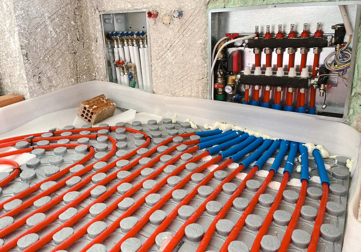
The completed disposition is therefore “flow criterion supported on the stated evidence; available-volume requirement unresolved.” Ask for the drawing-linked calculation and its boundary, not a verbal assurance that the flow path exists. No buffer size can be selected from this incomplete record, and a successful flow comparison is not whole-system acceptance.
Change the volume input: the designer provides a signed, applicable calculation showing the included segments, relevant valve states and exclusions against the exact source requirement. The volume gap can then be reviewed on that evidence. It does not erase the need for the separately documented flow result. Preserve both references so a later change to zoning or pipework triggers the appropriate reassessment.
| Record | Available evidence | Bounded decision |
|---|---|---|
| A | 24 L/min all-open loop-flow sum; source-side closed-state evidence missing | Source minimum-flow acceptance unresolved |
| B | Assumed applicable named 20 L/min criterion; matching-state record 8 L/min | Criterion not met; refer interface for professional review |
| C | Source-flow criterion supported; accessible volume and exclusions undocumented | Flow comparison supported; volume assessment unresolved |
Reconcile room demand with the heat source’s operating sequence
The general manifold commissioning guide describes proving the room-control sequence and stopping demand when thermostats are satisfied. That demand-side description must not be read as permission to defeat an exact heat source’s required circulation or protective functions. The applicable manufacturer sequence governs states such as defrost and protection, and any required post-run operation.
Ask the responsible designer to reconcile the source sequence with the proposed thermostat, actuator and pump-control states. The deliverable is a documented interface, not a generic promise that “all thermostats off” means every pump can always stop. Leave protection, interlocks, wiring and settings to the qualified parties using the actual installation instructions.
An unresolved sequence is a specific missing item, not evidence that a manifold is defective. Record who must answer it and which drawing revision their answer covers. If zoning changes after the review, check whether the relevant closable states, water path or counted volume have changed before reusing an earlier acceptance record.
| Document question | Evidence needed | Responsible route |
|---|---|---|
| Source requirements | Exact source model and applicable complete manual | Heat-source manufacturer and designer |
| Valve states and operating sequence | Drawing-linked control schedule and relevant professional records | Appointed designer and installer |
| Available water volume | Calculation boundary, included segments and manufacturer exclusions | Responsible designer |
| Manifold and actuator interface | Offered model data and project component schedule | Component supplier, with professional interface confirmation |
Send the manifold and controls supplier an answerable interface sheet
WARMHAUS has actual underfloor manifold and thermostat and electrothermal actuator product routes. Ask about the exact manifold/control interface against the project documents. Availability, actuator type and voltage, connection details and model-specific operating data need confirmation for the offered items; do not infer them from a generic control illustration.

Send the source model and manual revision, hydraulic drawing, manifold and loop identifiers, thermostat-to-actuator schedule, valves that may close and the responsible designer’s flow/volume requirements. Mark open technical questions explicitly. That lets the component enquiry distinguish a physical manifold/control matching question from an unresolved heat-source design decision.
Request the relevant manifold and actuator documentation and confirm the scope of supply. This article does not establish a WARMHAUS heat-pump or buffer offer, a system-design certification service, universal compatibility, savings or a commissioning guarantee. The heat-source manufacturer and the appointed design and installation professionals remain responsible for qualifying the actual arrangement.
Conclusion
Issue the interface sheet with three explicit dispositions: what the all-open record establishes, whether the relevant source-flow criterion is supported and whether accessible volume is documented. Assign each remaining question to the responsible professional. Finalise the manifold/control enquiry only against the confirmed interface, preserving the evidence and drawing revisions used.
Frequently Asked Questions
Can I add the loop flow-meter readings to prove heat-source flow?
Only if the responsible professional establishes that the measurement and circuit arrangement actually represent the required source flow. A secondary-loop sum alone is insufficient evidence.
Does passing minimum flow prove enough water volume?
No. Record the source-side flow evidence and the separate available-volume calculation against the exact manufacturer requirements.
Are 20 L and 20 L/min universal heat-pump requirements?
No. They are distinct examples from the named September 2021 Daikin manual, not WARMHAUS figures or targets for other models.
Should I remove an actuator or change a bypass to keep flow?
Do not use this document review as an adjustment instruction. Refer any proposed hydraulic or control change to the responsible qualified professional using the actual manufacturer instructions.
Written by Justin · WARMHAUS technical buying guides