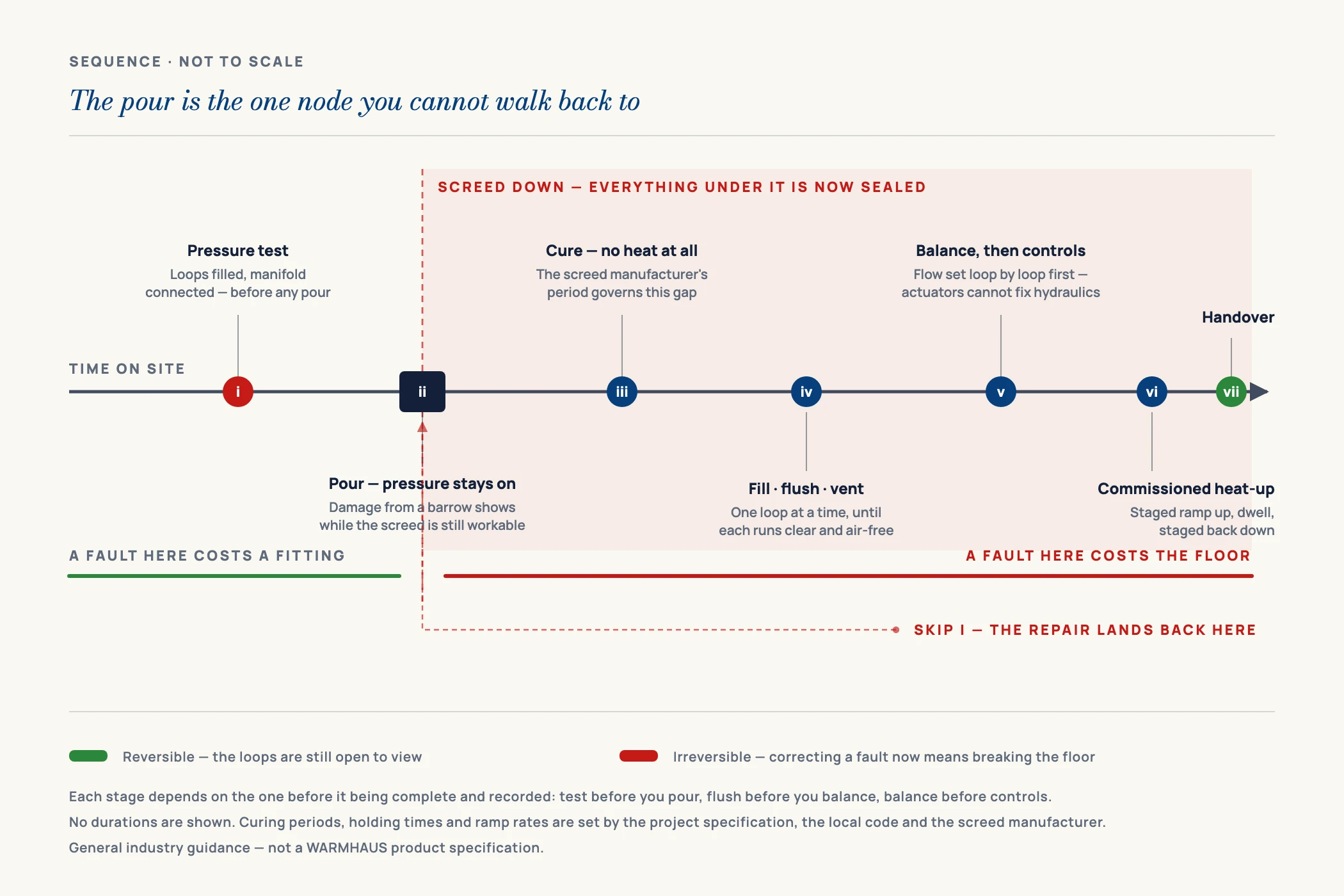
Commissioning is not the last hour of an underfloor heating job — it is a sequence with a fixed order, and the order matters more than any single step in it. Pressure-test before the screed goes down, because after it cures a leak costs a floor instead of a fitting. Flush and vent before you balance, because a balancing figure taken with air in the loop is a fiction. Balance before you hand the system to the controls, because actuators cannot correct a hydraulic imbalance they cannot see. Get the sequence wrong and everything you do afterwards measures the wrong thing. This checklist walks the sequence in order, gives the hold points where you stop and record a number, and ends with the commissioning record that decides who pays when a floor runs cold in year two.
Across the Middle East, North Africa, Southern Europe and Latin America, underfloor heating is often commissioned by whoever laid the pipe, with no formal document at the end — which is precisely why disputes over cold rooms are so hard to settle. Everything below is general industry guidance. Test pressures, heat-up schedules and holding times are set by the project specification, the local code and the screed manufacturer; confirm the exact figures against the datasheet of the pipe, manifold and screed you are using before commissioning a live system.
I. The Commissioning Sequence — Why the Order Is Fixed
There are six stages, and each depends on the one before it being complete and recorded. The table is the core of this guide: the running order, the hold point at each stage, and the value you write down before moving on. Treat the “record” column as mandatory.
The hold-point column gives a typical band as well as the rule, because “as specified” is not usable on site when the specification is silent — and on a great many jobs it is. The bands tell you whether you are in the right order of magnitude: whether a pre-screed test is a matter of minutes or hours, whether a heat-up is three days or a fortnight. They do not override anything. Where the project specification, the local code or the screed manufacturer gives a figure, that figure wins, and the bands below are only there to tell you when a stated figure looks wrong enough to query.
| Stage | What happens | Hold point — do not proceed until | Typical band (guidance only) | What you record |
|---|---|---|---|---|
| 1. Pre-screed pressure test | Loops filled and pressurised with the manifold connected, before screed is poured | Pressure holds for the specified period with no drop attributable to a leak | Commonly around 1.5× working pressure, often in the region of 6 bar; held anywhere from ~30 minutes for a quick pre-pour proof to 24 hours where the specification calls for it | Test pressure, start time, end time, start and end reading, ambient temperature |
| 2. Pressure held through the pour | System left under pressure while screed is laid and during initial cure | Screed placed and cured per the screed manufacturer’s instruction, pressure still holding | Pressure left on for the pour and initial cure; cure before any heat is commonly ~21 days for sand/cement and ~7 days for anhydrite, but the screed manufacturer’s figure governs | Gauge reading before and after the pour, date of pour |
| 3. Fill, flush and vent | Loops flushed one at a time, air purged at the manifold air vents and via the fill/drain valves | Water runs clear and air-free from each loop individually; system pressure at design fill | Each loop flushed individually until it runs clear; domestic systems commonly refilled to ~1–1.5 bar cold | Fill pressure, confirmation each loop flushed, date |
| 4. Balance the loops | Flow meters set loop by loop to the design flow rate for each circuit | Every loop reads its design flow with the pump at design speed and all loops open | Design flow comes from the loop schedule, not from a rule of thumb; residential circuits commonly land around ~1.0–2.5 l/min each | Design flow and achieved flow for every loop, pump setting |
| 5. Controls and interlock | Actuators, thermostats, wiring centre and boiler/heat-pump interlock proved | Each thermostat drives the correct actuator and the correct loop warms — verified room by room | Allow several minutes per thermal actuator to stroke before judging a zone; every zone proved individually, none assumed from the wiring schedule | Thermostat-to-loop map, actuator test result per zone |
| 6. Commissioned heat-up | Controlled first heat-up of the screed following a staged temperature ramp | Ramp completed at the specified rate and dwell, then system set to design flow temperature | Commonly starts around 20–25 °C flow, rises in steps of roughly 5 °C per day to the design maximum, dwells there for several days, then steps back down — a total of one to three weeks depending on screed | Start temperature, daily steps, maximum temperature, dates, final flow temperature |
Values and stages are general industry guidance, not a WARMHAUS-specific specification, and the typical bands are given for orientation only — they are not a specification and not a substitute for one. Test pressures, holding periods, curing times and heat-up ramps are set by the project specification, the local code and the screed manufacturer, and those sources take precedence in every case. Always confirm against the datasheet of the pipe, manifold and screed you are using.
A stage with no number written against it has not been commissioned. It has only been done.
II. Stage 1–2: Pressure Testing Before and Through the Screed
The pre-screed pressure test is the most valuable hour in the whole job, because it is the last moment a leak is cheap. Once screed covers the loops, a weeping connection becomes a demolition job. Fill the loops, connect the test equipment at the manifold, bring the system to the test pressure specified for the project, and hold it for the specified period while you inspect every visible connection — particularly the pipe-to-manifold connections, the joints most often disturbed by other trades.
Three points decide whether the test means anything. First, temperature moves the gauge: water warming or cooling in an exposed slab changes pressure without any leak existing, so record ambient temperature alongside the readings and read a small drift against it rather than dismissing a genuine loss as “just the sun”.
Second — and this is the one that produces most false leak calls — plastic pipe loses pressure on its own. PEX and PERT are viscoelastic: pressurise a loop and the pipe expands slightly and continues to relax over the following minutes and hours, so the gauge falls with no leak anywhere in the system. The drop is largest at the start and tapers off, and it is entirely normal. This is why pressure-test procedures for plastic pipe are written differently from those for metal: they typically involve re-pressurising to the test pressure once or twice during an initial period to let the pipe take up its expansion, and only then starting the holding period against which a real leak is judged. A falling gauge in the first half hour on a fresh plastic system is the pipe, not the installation. A gauge still falling steadily after the pipe has settled, with ambient temperature stable, is a leak. Confusing the first for the second gets sound floors dug up; confusing the second for the first gets a leak buried under screed.
Third, leave the system under pressure through the pour and the initial cure. A loop damaged by a shovel or barrow wheel then shows on the gauge while the screed is still workable — the difference between a repair and a rebuild. Note the reading before and after the pour, and keep both. The specific test pressure, the number of re-pressurising cycles and the holding period all come from the pipe manufacturer’s procedure and the project specification; the pattern above is general industry practice for plastic pipe, not a substitute for either.
The methodology is shared with pipework testing generally; our own approach to hydrostatic testing on the production side is set out under quality control and pressure testing. What differs underfloor is only the consequence of skipping it.
III. Stage 3: Fill, Flush and Vent — Loop by Loop
Air is the reason most “faulty” underfloor systems are not faulty at all. An air pocket in a loop blocks circulation as effectively as a closed valve, and it produces exactly the symptom that generates the call-back: one cold room in an otherwise working house. The fix is procedural rather than technical — flush each loop individually, not all of them at once.
Close every loop on both the flow and return bars, then open a single loop and let water run through it to the fill/drain valve until it discharges clear and free of bubbles. Close that loop, open the next, repeat. Flushing with all loops open sends water down the path of least resistance — usually the shortest loop — and leaves air sitting in the longest, which is the circuit most likely to be the room that later runs cold. Once every loop has been flushed individually, open them all, bring the system to design fill pressure, and purge the manifold air vents. Air keeps coming out of solution over the first days of operation, so revisit the vents at the end of the heat-up.
IV. Stage 4–5: Balancing, Then Controls — In That Order
Balancing comes after flushing and before controls, and both halves of that sentence carry weight. Balance before the air is out and you are setting flow meters against a reading that changes the moment the air clears. Hand the system to the controls before it is balanced and you have asked thermostats to compensate for a hydraulic problem they have no authority over — an actuator can only open or close its loop, it cannot make a starved circuit carry more water. Set every loop to its design flow rate with the pump at design speed and all loops open, then record design and achieved flow for each circuit. The method and the flow calculation are covered in our guide to manifold installation and balancing.
Controls commissioning is where the most embarrassing defects hide, and they are almost always the same one: the thermostat is wired to the wrong loop. On a manifold with eight near-identical actuators, a crossed pair is invisible until somebody turns up the bedroom and the hallway gets warm. Prove it room by room instead of assuming the wiring schedule was followed. Call for heat from one thermostat only, wait for the actuator to open — thermal actuators take several minutes, so do not judge in thirty seconds — and confirm the correct loop is warming. Then move to the next zone. Write the thermostat-to-loop map onto the record and inside the cabinet door, where the next engineer will find it.
Prove the interlock in the same stage: with every thermostat satisfied, all actuators should close and the heat source and pump should stop rather than circulate against a closed manifold. A failed interlock never shows up as a fault, only as a fuel bill.
V. Stage 6: The First Heat-Up Is a Commissioning Step, Not a Test Run
Screed needs a controlled first heat-up, and this is where commissioning most often goes wrong through impatience. The screed must cure for the period its manufacturer specifies before any heat is applied at all — as general guidance commonly around 21 days for a sand/cement screed and about 7 days for anhydrite, though thickness and site conditions move both. Heat is then introduced at a low flow temperature, typically in the region of 20–25 °C, and raised in staged increments of roughly 5 °C per day to the design maximum, held there for a dwell of several days, and brought back down the same way before the system is set to its design flow temperature. End to end that is usually one to three weeks. Ramp rates, step sizes, dwell periods and curing times vary by screed type and thickness, and the screed manufacturer’s instruction takes precedence over any general figure here.
Rushing does two kinds of damage. Heating a screed that has not cured, or ramping too fast, risks cracking the floor — a defect that surfaces after the covering is laid and gets attributed to the heating system for the rest of the building’s life. Skipping the heat-up means the covering is laid over a screed still carrying construction moisture, which is a claim waiting to happen against whoever installed the heating. Record the start temperature, each daily step, the maximum, the dwell and the dates — that record is what shows the ramp was followed if the floor later cracks for an unrelated reason.
Two smaller points belong here. Re-vent the manifold at the end of the heat-up, because heating drives dissolved air out of solution and a system vented cold usually needs venting again warm — this is the single most common reason a system that balanced perfectly on Friday has a cold loop on Monday.
And re-check the flow meters with the system hot before sign-off. Be clear about why, because it is easy to state this wrongly. Flow meter scales are commonly calibrated at a reference temperature of around 20 °C, so every reading shifts slightly at working temperature — but that shift shifts every meter on the bar in the same direction, so it does not change the relative balance between loops, and it is not a reason to re-set anything. The full explanation is in our guide to manifold flow meters and how to read them. The reason to look again hot is different: air that has come out of solution during the heat-up, an actuator that has now stroked for the first time, or a pump that has settled onto a different point of its curve can all move a loop’s actual flow. You are re-checking the system, not correcting the scale. If a loop has genuinely moved, re-balance it and note the change on the record.
VI. The Commissioning Record — What You Hand Over
The document is the deliverable. In any dispute, a system with no commissioning record is indistinguishable from one that was never commissioned — and the party without paperwork is the party that pays. These are the items worth having on the sheet before anybody signs.
Pressure test certificate
Test pressure, start and end readings, holding period, dates and ambient temperature — for the pre-screed test and the reading held through the pour. It proves the installation was sound before it was covered, which moves the burden of proof for any later leak.
Loop schedule — length, area and room
Every loop numbered against the room it serves, with its pipe length and floor area. Without it, the next engineer to open the cabinet is guessing and fault-finding starts from zero.
Balancing record — design vs achieved flow
Design flow rate and the flow actually achieved for each loop, with the pump setting. It separates a system set up correctly from one later disturbed, and shows at a glance whether a cold room was ever balanced.
Thermostat-to-loop map
Which thermostat drives which actuator on which loop, verified by test rather than copied from the design. Crossed zones are the most common controls defect and the hardest to diagnose without a map.
Heat-up log
Curing period observed, start temperature, each staged increment with dates, maximum temperature and dwell, and the final design flow temperature. This is the defence against a screed-cracking claim.
Component schedule and settings
Manifold size and configuration, pump and mixing unit model and setting, actuator type, thermostat models, and the design flow temperature the system was left at. It makes spares a lookup rather than a site visit.
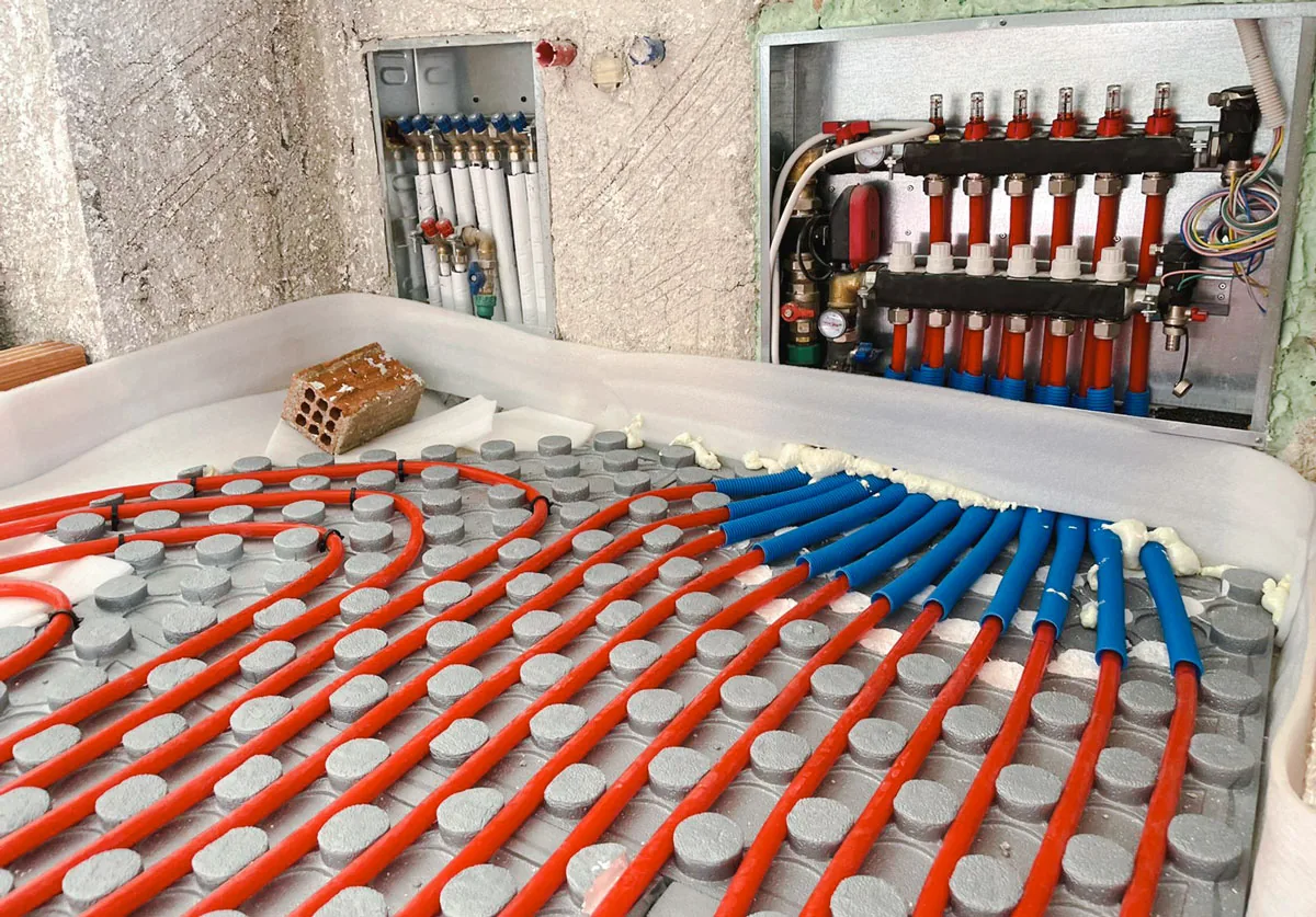
Photographs of the loops before the pour
Overhead images of each room’s pipe layout with a scale reference, taken before screed. If anyone ever needs to drill or lift the floor, these are the only record of where the pipe runs.
Handover briefing to the end user
How the thermostats work, why underfloor heating responds slowly, why deep overnight setback is usually counter-productive, and where the manifold and its isolation valves are. Many first-season complaints are expectations, not defects.
The tools needed to produce this record are unremarkable: a pressure test kit and gauge, a means of flushing and filling, the flow meters already built into the manifold, and something to write on. Where a project requires the installer to supply the test equipment alongside the system, our tool range is quoted on the same order as the pipe and manifolds.
VII. Manifolds That Make Commissioning Straightforward
Most of what makes commissioning painful is decided at specification, not on site. A manifold with flow meters on every circuit makes stage 4 a measurement instead of an estimate. Isolation on both flow and return bars is what allows loop-by-loop flushing at stage 3. Fill and drain valves and air vents integrated at the manifold are what let one person purge the system without improvising. And actuator threads that match the actuators actually being fitted are what keep stage 5 from becoming an adapter hunt.
WARMHAUS builds the manifold, the loop pipe and the controls — we are a manufacturer of PPR, PEX and brass piping systems, not a trading company, with our own extrusion, injection-moulding and machining lines. That matters at commissioning for one specific reason: when the brass manifold, the PEX or PERT loop pipe and the actuators and thermostats are specified together from one source, the connection sizes, actuator threads and flow-meter ranges are matched before the crate is packed rather than reconciled on site. Manufacturing since 1993, ISO 9001 / ISO 14001 / ISO 45001 certified, EU CE marked and SGS tested, with no MOQ and a standard lead time of 45 days — certificate documents available on request.
Tell us the project’s loop counts, manifold sizes and control type, and we will send the manifold specifications, the matching pipe and controls range, and distributor terms. Request the manifold and controls specifications for your project