A floor with cold corners is almost never a boiler problem. It is a flow problem, and the underfloor heating manifold flow meter is the component that lets you see it and fix it. Water takes the easy path: left to itself, most of the flow rushes down the short loops and starves the long ones, so one end of the room reaches setpoint while the other stays cool. A flow meter puts a number on each circuit — litres per minute, read off a scale — so an installer can force fair shares instead of guessing at valve turns. This guide explains how the flow meter works, how to read and set it, what flow rates to aim for, how to specify one when you are buying manifolds, and the faults that make a meter lie.
It is written for installers commissioning a floor and for the importers deciding which underfloor heating manifold to put in a container. All figures here are general industry guidance, not a specification for any one product — the numbers that govern a real system come from the project’s loop schedule and the datasheet of the manifold you are installing.
I. What a Flow Meter Is — and What It Is Not
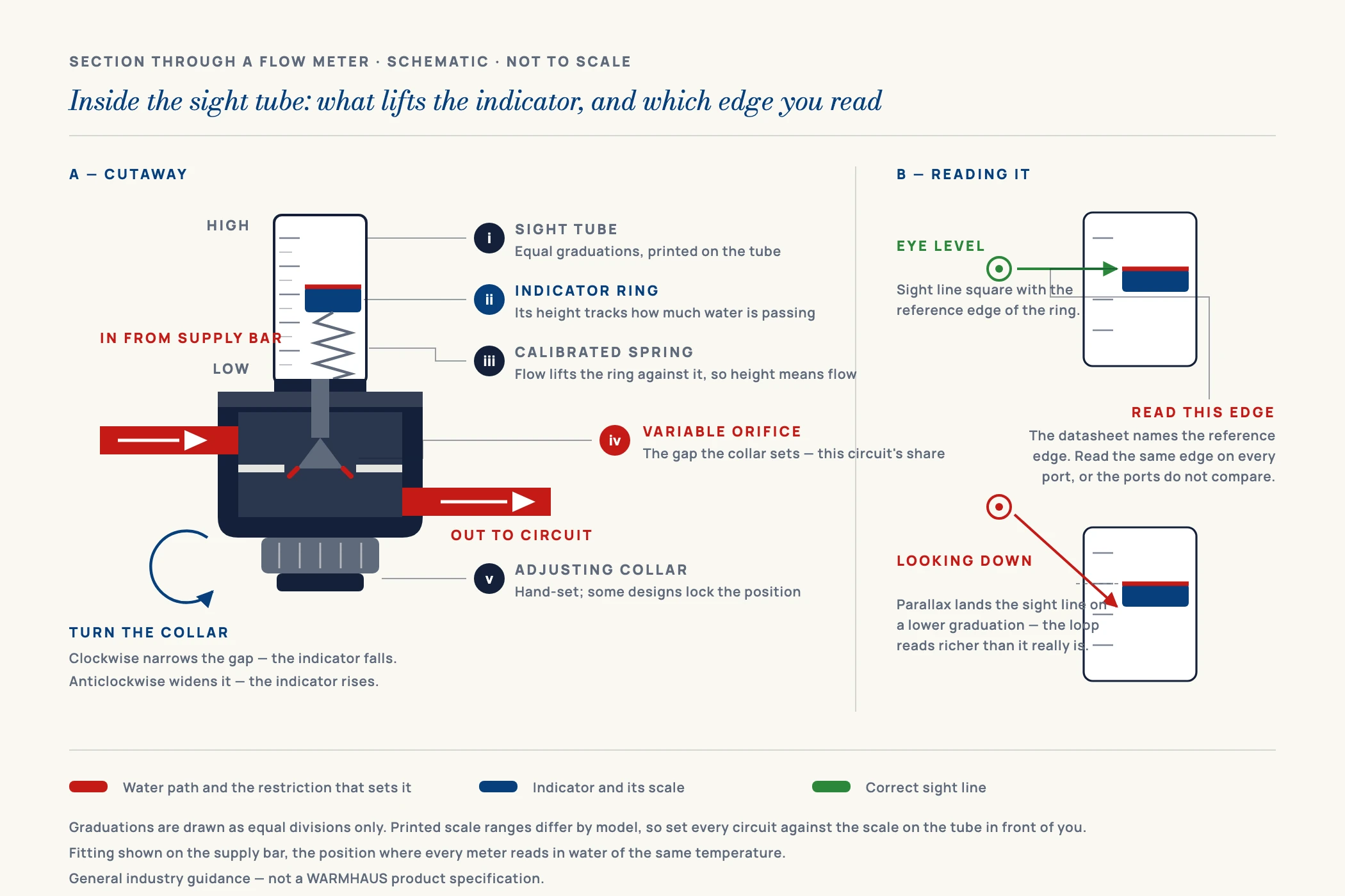
A flow meter on an underfloor heating manifold is a combined indicator and regulating valve fitted to each circuit port. Inside a transparent sight tube sits a small float or indicator cap riding on a calibrated spring. Water flowing through the port pushes the float up the scale; the higher it sits, the more litres per minute are passing. Turn the adjusting collar and you restrict or open the port — the float moves, and you have set the circuit.
Two things it is not. It is not a heat meter: it reports volume, not energy, and two loops at identical flow deliver different heat if their lengths or floor build-ups differ. And it is not a service shut-off — most designs close fully, but isolation for repair belongs to the manifold’s main ball valves, not to a component set to a commissioning figure.
A flow meter does not make a floor warmer. It makes the warmth land where the design said it should.
Position matters for how you read the scale. Flow meters are commonly fitted on the supply bar, with the actuators and thermostatic heads on the return, though both arrangements exist. The scale on many meters is calibrated at a reference water temperature — typically around 20 °C — so the reading at operating temperature drifts slightly from the printed value.
It is worth being precise about that drift, because the usual shorthand — “it affects every loop equally, so ignore it” — is only half true. It holds where the meters sit on the supply bar: every circuit is fed from the same header at the same temperature, so every float is reading in water of the same density and viscosity, and the offset really is common to the whole bar. It does not hold on a return-mounted set, where each loop comes back at its own temperature: a starved long circuit returns much cooler than a short one, so the offsets differ loop by loop and the comparison you are relying on is no longer like-for-like. This is a second and rarely stated reason to prefer flow meters on the supply bar. Even then the correction is small relative to the tolerance of the meter itself, so general practice is to balance to the printed scale and not attempt a temperature correction — but the justification is the common supply temperature, not an assumption that the drift cancels everywhere. Where a datasheet gives a correction factor for operating temperature, use it.
II. Typical Flow Rates and Flow Meter Ranges
The two questions installers ask are “what range should the meter cover?” and “what should I set each loop to?”. The table below answers the first and frames the second. Flow follows loop length and heat load: a long circuit has more resistance and carries more floor area, so it needs more flow than a short one to deliver the same result. These are typical values used for general guidance in residential and light commercial radiant floors — confirm every figure against the actual manifold datasheet and the project’s loop schedule before you commission.
| Item | Typical value / range | What it means in practice |
|---|---|---|
| Flow meter scale range | 0–2 l/min · 0–4 l/min · 0–5 l/min | 0–2 l/min suits small residential loops; 0–4 or 0–5 l/min covers larger circuits and mixed projects |
| Typical loop flow, residential | ~1.0–2.5 l/min per circuit | Most domestic loops land inside a 0–4 l/min scale with headroom to adjust |
| Design temperature difference (ΔT) | ~5–10 K between flow and return | Flow rate is set to hold the design ΔT; a wide ΔT means flow is too low |
| Supply temperature, radiant floor | ~35–45 °C typical | Low-temperature operation — the reason mixing groups exist on the manifold |
| Scale reference temperature | Commonly calibrated ~20 °C | Readings drift slightly at operating temperature; the offset is common to all loops only on a supply-mounted set |
| Sight tube body material | Polymer, transparent | Must be chemically compatible with the system fluid, including glycol mixes |
| Adjustment | Manual collar, by hand, no tool | Set and hold; some designs offer a memory or lock position |
Values are general industry guidance, not a WARMHAUS-specific specification. Target flow per loop is a design output — it depends on loop length, pipe spacing, floor construction and design heat load — so always work to the project’s loop schedule and confirm against the datasheet of the manifold and pipe you are actually using.
Read the table as a sizing filter rather than a setting list. If a project’s loops are mostly 60–90 m of 16 mm pipe, a 0–4 l/min meter puts every circuit in the middle third of the scale, where a float is easiest to read and trim. Fit that same meter to a hall circuit wanting 3.8 l/min and you are at the top of the scale with nowhere to go. Choosing the scale is part of specifying the manifold, not an afterthought.
Note what the table deliberately does not contain: a maximum loop length. Planning figures by pipe diameter are set out in our guide to underfloor heating pipe spacing and loop length, and that is the single reference this cluster works to. The reason it belongs there and not here is that loop length is not a property of the pipe — it is a property of the hydraulics. What actually caps a circuit is the pressure loss the circulator can overcome at the flow that circuit needs. The same 16 mm pipe therefore supports a materially shorter loop at 2.5 l/min than at 1.0 l/min, because pressure loss climbs far faster than flow does. A quiet bedroom loop and a hall loop drawn from the same coil are not entitled to the same length, and treating the diameter figure as a hard ceiling is how loops get split when they did not need to be — or run long on the assumption that the number is a guarantee.
III. How to Read and Set a Flow Meter
Balancing with flow meters is a read-and-set job, done in a defined order. Rushing it, or doing only one pass, is why floors come back in the first cold week.
I. Get the system into a stable reading state
Fill, vent and pressure-test the system first. Air in a circuit lifts the float erratically and makes every reading worthless. Then run the circulating pump and open every zone — all actuators energised or heads removed — so all circuits are calling at once. A meter read with half the manifold closed will not hold its value when the rest opens.
II. Read the float against the scale, at eye level
Read the top edge of the float on a vertical meter, or the indicator line on a horizontal design — the datasheet shows which edge is the reference. Read at eye level: looking down at the tube exaggerates the value. Record every circuit before you adjust anything, so you know which loops are being starved and by how much.
III. Set the long loops first, then throttle the short ones
Open the longest, highest-demand circuits fully, then bring the short ones down towards their target. Working in this direction keeps the pump serving the loops that need the most head, rather than trapping you in a cycle of opening everything and finding the differential has vanished.
IV. Do a second and third pass
Every adjustment shifts the others: throttling one circuit raises the differential across the bar and pushes the remaining floats up. Repeat the whole sweep until a full pass produces no meaningful change. Two passes is a minimum; three is normal on a manifold with eight or more ports.
V. Log the readings and hand them over
Write the final l/min per port into the commissioning record with the loop numbers and lengths. This is the document that lets the next person diagnose a cold room in two minutes instead of two hours, and on tendered projects it is often a condition of handover. If the manifold offers a memory or lock setting on the collar, engage it so cleaning or a curious occupant does not undo the work.
IV. Six Reasons a Flow Meter Reads Wrong
When a balanced manifold still produces a cold room, the meter is usually telling the truth about a problem elsewhere — but not always. This is the list to work through before you blame the design.
Air trapped in the circuit
The float jumps, sits high, or hangs at zero while the loop is clearly warm. Fix: vent the manifold and purge the circuit loop by loop with the others closed, then re-read once the float is steady.
Reading with zones closed
With only two circuits open, the differential across the bar is high and every float reads generously. Fix: balance with all zones calling, then verify a second time under normal control operation.
Debris on the float or seat
Installation swarf, jointing residue or system dirt sticks the float or holds the seat partly open, so the reading no longer tracks the setting. Fix: flush the system properly before commissioning and fit the strainer the manifold provides.
Meter scale too large for the loops
Every circuit sits in the bottom sixth of a 0–5 l/min tube, where the graduations are tight and a 0.3 l/min error is invisible. Fix: specify the scale against the project’s expected loop flows before ordering.
Pump head or curve set wrong
No amount of collar adjustment fixes a pump that cannot deliver the total design flow against the manifold’s resistance. Fix: check the pump duty and control mode against the design before re-balancing.
Loop lengths that do not match the schedule
A circuit run longer than drawn will not reach its target flow however far you open it, and the meter is simply reporting that. Fix: measure the actual pipe used per loop at first fix and record it — this is the number balancing depends on.
V. What to Specify When You Buy Manifolds with Flow Meters
For an importer, the flow meter is a small part with an outsized effect on complaints: one that fogs, sticks or loses its setting generates warranty traffic long after the container has cleared. These are the points worth pinning down before a purchase order.
Scale range and graduation. Ask which ranges are offered and how finely the tube is graduated. Match the range to the loop sizes your market actually installs — apartment retrofits and villa projects sit in different bands.
Body and sight-tube material, and fluid compatibility. The transparent tube is the part most exposed to system chemistry. If your market uses glycol antifreeze mixes, confirm compatibility explicitly rather than assuming it.
Adjustment and memory. Confirm the collar can be set by hand without a tool, and whether the design holds its setting when a circuit is isolated and re-opened.
Port thread, centres and compatibility with your pipe. The meter has to land on a bar whose port thread and spacing match the compression or press adaptors your manifold ships with, and those adaptors have to fit the pipe you are selling alongside it. This is the mismatch that turns a clean shipment into a site problem.
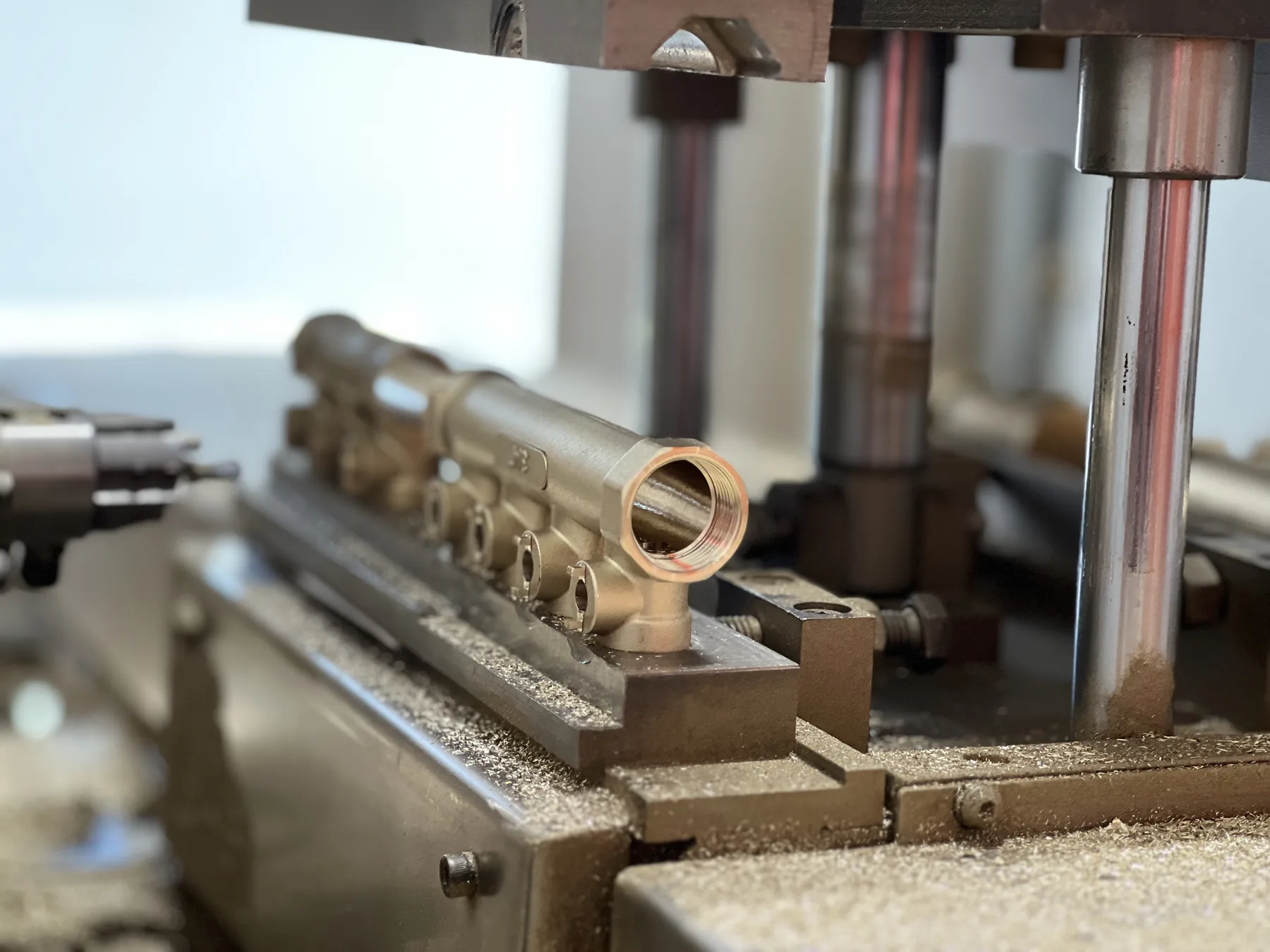
Bar material and machining. The meter is only as good as the port it screws into. A cleanly machined brass manifold bar with consistent thread quality is what makes a meter seat square and read repeatably across every port.
Controls interface on the opposite bar. Flow meters set the hydraulics; actuators and thermostats decide when each circuit runs. Check that the return-bar valve thread matches the actuators and thermostats you intend to pair with it — a mismatched actuator thread is a common and entirely avoidable field failure.
VI. One Source for the Manifold, the Meters and the Controls
The recurring theme in every fault above is a mismatch between parts that were bought separately: a meter scale wrong for the loops, an adaptor that does not suit the pipe, an actuator thread that does not match the return bar. WARMHAUS is a manufacturer of PPR, PEX and brass piping systems, not a trading company — the extrusion, injection-moulding and machining lines are our own, which is why the manifold bar, the flow meter ports, the loop adaptors and the control valve threads are held to one internal standard rather than averaged across three suppliers. That matters most on a mixed container, where the manifolds, the brass manifold range, the PEX loop pipe and the thermostats and actuators must all fit each other on arrival.
Manufacturing since 1993, ISO 9001 / ISO 14001 / ISO 45001 certified, EU CE marked and SGS tested, with brass drawn from 57-3 and CW617 stock and polymer raw material from Hyosung, Borealis and LG. No MOQ, so a first order can be a trial mix of manifold sizes rather than a pallet of one part number; standard lead time 45 days on planned production slots. If a step in this guide is close to what you need but not exactly it, tell us the markets you supply and the loop sizes you install — Request the manifold and flow meter specifications . Certificates, port dimensions and detailed technical data: available on request.