A radiant floor is designed with two numbers. Pipe spacing — the centre-to-centre distance between adjacent runs — decides how much heat the floor delivers per square metre and how even the surface feels underfoot. Loop length — the developed length of one circuit from manifold flow port back to return port — decides the pressure drop, and therefore whether the circulator can push design flow through that circuit at all. Get the spacing wrong and the room is short of output or striped with warm and cool bands; get the loop length wrong and the far end runs cold whatever the thermostat asks for. Neither is fixable once the screed is down.
This guide is for the people who commit to those numbers before the pipe is unrolled: the specifier producing a layout drawing and the installer setting out clips on site. All figures below are general industry guidance for planning. The binding values come from the project’s own heat-loss calculation and the datasheets of the pipe, manifold and heat source in use.
I. What Pipe Spacing Actually Controls
Spacing is written as a pitch in millimetres — 100, 150, 200, 300 mm — measured centre to centre between neighbouring runs. It sets heat output per square metre at a given flow temperature, because it sets how much pipe surface sits under each square metre of floor. Halve the pitch and you roughly double the pipe per square metre. Tighter spacing therefore meets a demanding heat load without raising flow temperature — which matters when the heat source is a condensing boiler or a heat pump whose efficiency falls as flow temperature climbs.
Spacing also controls surface temperature uniformity. Heat spreads laterally through the screed before reaching the surface, so when the pitch is wide relative to the screed thickness above the pipe, the floor develops a temperature ripple — warm above the pipe, cooler between runs. Barefoot occupants in a bathroom notice it; nobody does in a warehouse.
Spacing is not a comfort preference. It is the lever that buys output without raising flow temperature — and flow temperature is what your heat source charges you for.
Cost runs in both directions: tighter spacing consumes more pipe and labour but allows a lower flow temperature. Across several thousand square metres that is worth calculating, which is why underfloor heating system planning treats output and pitch as one decision.
II. Pipe Spacing and Loop Length — Planning Table
The table combines both numbers: what each pitch is used for, how much pipe it consumes per square metre, and how much floor one loop covers before hitting the length ceiling. Both derived columns come from the pitch by arithmetic, so they can be checked. Pipe per m² = 1 ÷ pitch in metres — at 150 mm centres, 1 ÷ 0.15 ≈ 6.7 linear metres per square metre. Gross area per loop = loop length × pitch — at 150 mm centres a 100–120 m loop covers 15–18 m². The area column below is gross floor covered by the pipe in the room; the tail run out to the manifold and back is not included and must be subtracted from the loop length before the area is worked out. On a real circuit with a 10 m tail the usable area is correspondingly smaller.
| Pipe spacing (centres) | Pipe per m² (approx.) | Typical application | Relative output | Gross area per loop, 16 mm pipe (100–120 m, tail excluded) |
|---|---|---|---|---|
| 100 mm | ~10.0 m | Bathrooms, wet rooms, perimeter and glazed zones | Highest | ~10–12 m² |
| 150 mm | ~6.7 m | Living areas, bedrooms — the common default | High | ~15–18 m² |
| 200 mm | ~5.0 m | Well-insulated rooms, upper floors, low-load spaces | Moderate | ~20–24 m² |
| 250 mm | ~4.0 m | Large open areas, warehouse and industrial slabs | Lower | ~25–30 m² |
| 300 mm | ~3.3 m | Frost protection, tempering, intermittent-use space | Lowest | ~30–36 m² |
Values are general industry guidance, not a WARMHAUS-specific specification. The area column is arithmetic from the loop-length band in section III and assumes the whole loop is laid in the room; deduct the tail run before applying it. Achievable output at any pitch depends on flow temperature, screed type and thickness, floor covering resistance and insulation below the slab. Always confirm against the pipe datasheet and the project heat-loss calculation.
III. The Loop Length Ceiling — and Why It Exists
The maximum length is not an arbitrary convention. Water loses pressure to friction along the run, so the longer the loop, the greater the pressure drop the circulator must overcome to deliver design flow. Push past the point where available pump head runs out and flow falls below design — the water gives up its heat too early and the tail end delivers little. That is the cold patch in the far corner, and no thermostat setting corrects it. A second effect compounds it: along a very long loop the water cools progressively, widening the difference between start and end beyond the design temperature drop.
Both argue for the same discipline — cap the length, and split the area into more circuits rather than fewer long ones. The ceiling scales with diameter: a larger bore drops less pressure per metre.
| Pipe outside diameter | Typical maximum loop length | Where it is normally used | Practical note |
|---|---|---|---|
| 12 mm | ~60–80 m | Thin-profile and overlay systems, retrofit boards | Short loops only; more circuits per area |
| 16 mm | ~100–120 m | Mainstream residential screed floor | Reference size for most spacing tables |
| 17 mm | ~110–130 m | Residential and light commercial screed | Slightly more reach than 16 mm |
| 20 mm | ~120–150 m | Larger rooms, commercial and industrial slabs | More output per loop, stiffer at tight pitch |
General industry planning guidance only. Actual limits depend on pipe wall dimensions and bore, design flow rate and temperature drop, available circulator head and the tail run to the manifold. Confirm against the pipe datasheet and the system’s own hydraulic calculation.
Two rules travel with that table. First, the tail counts: the run from the manifold to where the loop starts serving the room, and back, is part of the length — a manifold sited far from the room it feeds can consume twenty metres of the ceiling before a single square metre is heated. Second, keep loops in one zone within a similar length of each other, since very different lengths mean very different resistances and force the balancing valves to the extremes of their range. Sizing the underfloor heating manifold is the same exercise from the other end.
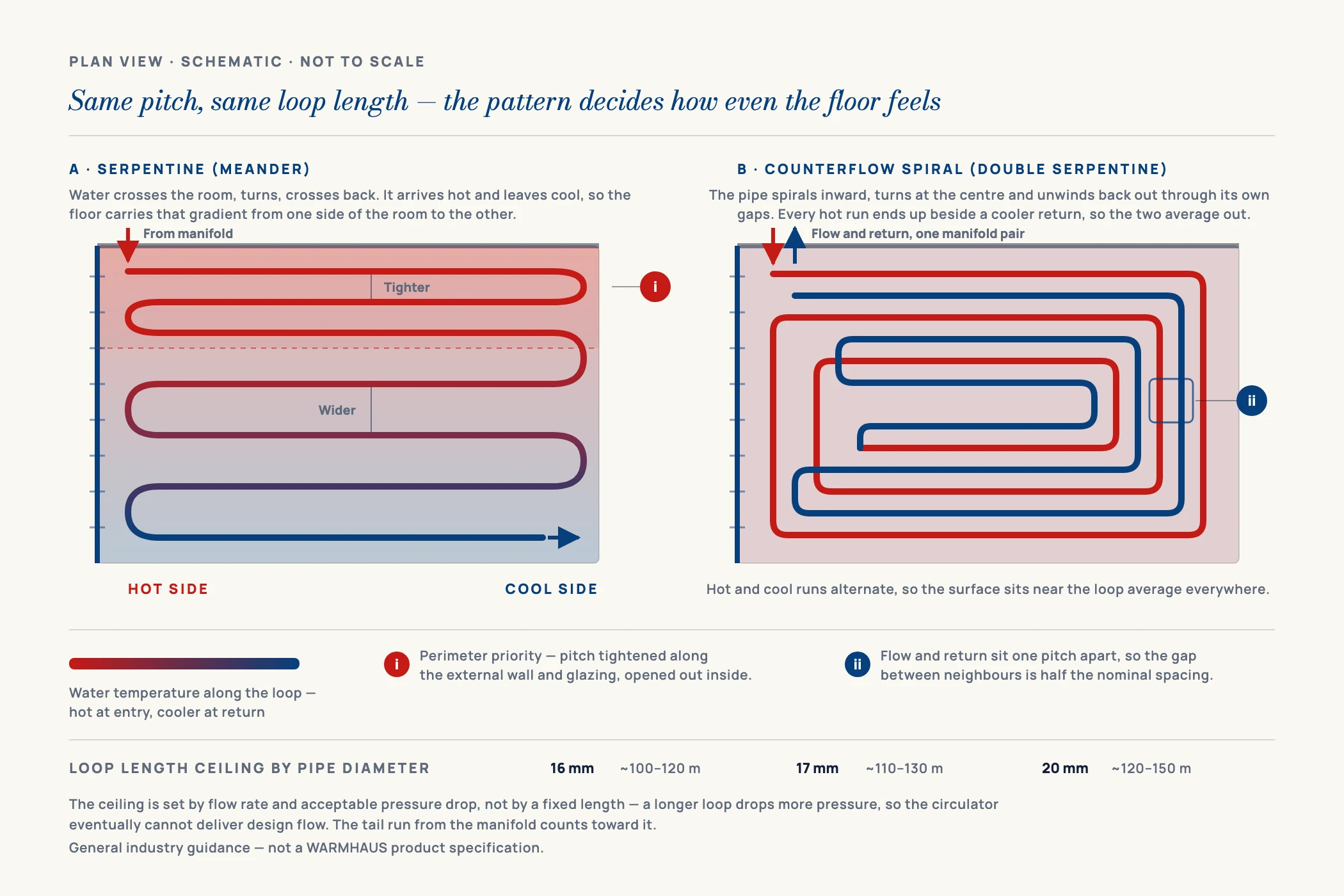
IV. Layout Patterns: Serpentine, Counterflow and Perimeter Priority
Spacing tells you how far apart the runs sit; the layout pattern tells you which order they are laid in, and it changes how heat is distributed even at identical pitch.
I. Serpentine (meander)
The pipe runs back and forth in parallel lines — the simplest pattern to set out and the least wasteful of pipe. Its weakness is that water enters hot at one edge and leaves cooler at the other, giving the room a warm side and a cool side. That is acceptable where the gradient can be aimed usefully: start the loop along the coldest wall or the glazed façade, so the hottest water lands where heat loss is highest.
II. Counterflow (double serpentine or spiral)
Flow and return legs run alongside each other, so every hot run is paired with a cooler return and the local average stays nearly constant. That gives a much more even surface temperature, and it is the default where uniformity matters. The cost is a more demanding set-out: the gap between any pipe and its immediate neighbour is half the nominal spacing, so the bends are tighter than they look on the drawing.
III. Perimeter priority
Less a separate pattern than a modifier on the others: the first runs are laid at a tighter pitch along external walls and under large glazing, then the pitch opens out across the interior. This puts the highest output where the heat loss is, and avoids over-heating the middle of the floor to compensate for a cold edge.
Whichever pattern is used, respect the minimum bend radius of the pipe, stated on the datasheet as a multiple of outside diameter. Bending tighter kinks the wall and restricts the bore, leaving a permanent weak point in a circuit that stays buried for the life of the building.
V. Working Out the Pipe Quantity for a Floor
Once spacing and loop length are fixed, the material take-off is arithmetic — and doing it properly at quotation stage is what stops a delivery arriving a coil short.
Take the heated area, not the room area
Subtract fixed kitchen units, built-in wardrobes and baths. Pipe is not laid under them, and including them inflates every figure downstream.
Multiply by the pipe consumption for your pitch
About 10 m per m² at 100 mm centres, 6.7 m at 150 mm, 5.0 m at 200 mm. With perimeter priority, calculate the tighter edge band and the open interior separately.
Add the tail run for every loop
Measure flow and return from the manifold to the start of each circuit and double it. With a remote plant room this is the item most often forgotten.
Divide into loops that respect the length ceiling
Developed length per circuit, tails included, stays under the limit for your diameter. If a room needs two loops, split it into equal halves rather than one long and one short.
Keep each loop in one continuous length
No joints under the screed, so every loop is cut from a single coil. A 200 m coil does not yield two clean 100 m loops once tails are added.
Add wastage and round up to whole coils
Set-out losses and offcuts are normal. Order in the coil lengths actually supplied, and confirm available coil sizes before finalising the take-off.
A worked example, and it is worth following the arithmetic because it shows where the tail eats the ceiling. A 40 m² living room at 150 mm centres needs roughly 40 × 6.7 = 268 m of pipe in the floor. With 16 mm pipe held near the middle of its 100–120 m band and a 10 m flow-and-return tail per circuit, the floor pipe available per loop is about 110 − 10 = 100 m, so 268 ÷ 100 rounds up to three circuits. Three loops of about 89 m in the floor, plus the 10 m tail, is roughly 99 m developed length each — inside the ceiling, and three circuits of near-identical length, which is what makes the manifold straightforward to balance. Check it against the table: 89 m at 150 mm centres covers 89 × 0.15 ≈ 13.3 m², and 3 × 13.3 ≈ 40 m². That is the same 15–18 m² gross figure from the table, reduced by the tail exactly as the note under it says.
VI. Six Spacing and Loop Errors That Surface After the Pour
These cannot be corrected without breaking concrete, which is why they are worth checking at design stage.
One pitch applied to the whole building. A bathroom, a north-facing glazed lounge and an internal bedroom have different heat losses. Laying all three at a convenient 150 mm leaves one under-served and another over-piped. Pitch follows the heat-loss calculation, room by room.
Ignoring the floor covering. Thermal resistance above the pipe is part of the output calculation: a floor destined for thick carpet or heavy timber needs tighter spacing, or a higher flow temperature, than the same floor in tile. When the covering is chosen after the pipe is buried, design for the worst case the client might pick.
Loops of very unequal length on one manifold. Balancing valves have a working range, and circuits differing by a factor of two push it to the extremes. Split areas into similar-length circuits from the outset.
Forgetting the tails. A circuit measured only across the room it serves, then run twenty metres back to a distant manifold, quietly breaks the length ceiling.
Crossing movement joints unprotected. Where a circuit crosses a structural or screed movement joint it needs a sleeve, so the slab can move without loading the pipe. Better still, keep each circuit within one screed bay and let only the sleeved tails cross.
Set-out drift on site. A pitch that starts at 150 mm and wanders to 200 mm across a large room removes output from part of the floor. Clip rail, staple systems and printed grids all exist to stop this, and pipe with reliable coil memory and good flexibility — the qualities that matter most in PEX pipe for underfloor heating — makes holding the line easier.
VII. Pipe and Manifold Specified as One Set
Spacing and loop length only survive contact with a real project if the components behave the way the drawing assumed. Pipe that holds its stated dimensions coil after coil keeps the pressure-drop calculation honest, and adapters that match the pipe outside diameter keep the manifold connection leak-free.
WARMHAUS manufactures the pipe and the brass manifolds it connects to. We are a manufacturer of PPR, PEX and brass piping systems, not a trading company — the extrusion, injection-moulding and machining lines are our own, which is why pipe dimensions and manifold adapter threads are held to one internal standard rather than averaged across three suppliers. Raw material comes from Hyosung, Borealis and LG. Manufacturing since 1993, ISO 9001 / ISO 14001 / ISO 45001 certified, EU CE marked and SGS tested, with no MOQ — so a distributor can trial a floor package before committing to volume, and mix pipe, manifolds and fittings into one consignment instead of opening three supplier accounts. Standard lead time 45 days.
Tell us the pipe diameters and coil lengths your market specifies, and the manifold port counts you stock. Request the underfloor heating pipe and manifold specifications and we will send dimensions, coil options, the matching adapter range and distributor terms. Pricing and certificate documents available on request.