Underfloor heating fails in one of two ways at the mixing group: either the loops never get warm, or they get far too warm. Both are the same fault seen from opposite sides — the pump and mixing valve unit is not doing its job. A heat source designed around radiators delivers water at a temperature a screed floor cannot tolerate, and something has to sit between them and reduce it. That something is the mixing unit: a blending valve, a circulation pump, and usually a temperature sensor and safety limiter, assembled as one group that bolts onto the head of the underfloor heating manifold. This guide explains what each part does, the difference between thermostatic and motorised control, how to size the pump, and the physical dimensions that decide compatibility.
This is written for importers and distributors quoting complete radiant packages, and for the installers commissioning them. All temperature, flow and head figures below are stated as general industry guidance, not WARMHAUS specifications — always confirm the exact figures against the technical datasheet of the pump, valve and pipe you are actually using.
I. Why a Mixing Unit Exists at All
The problem is a temperature mismatch. Most heat sources in mixed systems — a boiler also feeding radiators or a cylinder — run a flow temperature far above what a floor construction can accept. Screed, adhesive, timber and most floor coverings all have limits, and so does the person standing on the floor. Common practice is to hold the surface temperature of an occupied floor to roughly 27–29 °C, which puts the design flow temperature into the 35–45 °C band for most screed systems.
Feed 70 °C water straight into a loop and several things go wrong at once. The floor becomes uncomfortable and the screed sees thermal stress it was never designed for. Timber and vinyl coverings can move, cup or delaminate. And the pipe runs at the top of its temperature-and-pressure envelope for its entire service life rather than in the middle of it — the wrong way to treat a system meant to last decades inside a concrete slab.
A mixing group is not an accessory bolted onto a manifold. It is the component that makes a high-temperature heat source and a low-temperature floor into one system.
The second job is hydraulic separation. The heat source has its own circulator, sized for its own circuit. The underfloor circuit has a very different resistance profile: long runs of small-bore pipe, many parallel loops, low temperature difference. Running both from one pump means one circuit always wins and the other is starved. The mixing group carries its own pump so the floor circuit is driven independently of whatever the boiler is doing.
II. What Is Inside a Pump and Mixing Valve Unit
Terminology varies by market — mixing group, pump group, mixing station, blending set — but the functional parts are consistent.
The mixing valve
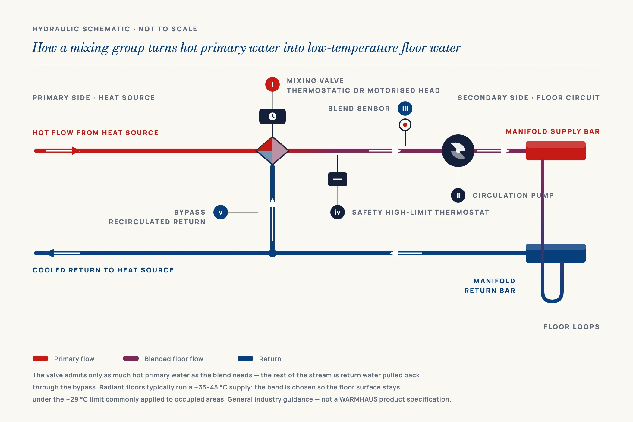
A three-port valve blending hot water from the heat source with cooler water from the manifold return. It is the temperature-setting element: everything downstream of it is at the blended temperature. Control is either thermostatic or motorised.
The circulation pump
Drives water around the loops against their combined resistance. Normally a wet-rotor circulator. Two port-to-port body lengths dominate the market — 180 mm, the common residential length, and 130 mm, standard on many compact mixing groups — and they are not interchangeable without changing the group’s pipework, so read the length off the drawing rather than assuming. Modern units are high-efficiency electronically commutated pumps running a constant- or proportional-pressure curve rather than fixed speeds.
The bypass or balancing arrangement
A path letting a proportion of the manifold return water re-enter the mix rather than travel back to the heat source. This is what makes low flow temperatures achievable, and why the return connection matters as much as the flow connection.
The safety high-limit thermostat
A contact thermostat clamped to the flow pipe downstream of the valve, wired to cut the pump or close the valve if the blended temperature exceeds a set ceiling. The last line of defence for the screed and the pipe if the mixing valve sticks — not optional in a screed system.
Flow and return thermometers
Usually in the ball valves or the manifold end caps. Without them commissioning is guesswork — you cannot verify the blended temperature or read the differential across the circuit.
Isolation valves and an air vent
Primary-side isolation lets the pump or valve be serviced without draining the loops. An automatic air vent at the high point prevents the trapped air that stops circulation in a set of loops for no visible reason.
Everything above hangs off the head of the manifold, so bar centres, thread sizes and the direction of the flow bar all have to agree. That compatibility question is covered in section V.
III. Thermostatic vs Motorised Mixing — Which Control to Specify
This is the decision that most affects both price and behaviour, and it is the one distributors are asked to explain most often.
I. Thermostatic mixing (fixed-point control)
A thermostatic mixing valve holds a temperature you dial in — say 40 °C — using a wax or liquid-filled cartridge that expands and contracts to move the valve spindle. No wiring, no controller, no outdoor sensor: it regulates purely on the temperature of the water passing through it.
The advantages are simplicity, cost and the fact that nothing can be mis-programmed. The limitation is that the setpoint stays fixed until somebody physically changes it. On a mild day the floor still receives 40 °C water and the room control compensates by cutting loops off with actuators, which produces a cycling, slightly uneven floor. For single-family housing, apartment fit-outs and most distributor stock packages, thermostatic control is the sensible default.
II. Motorised mixing (weather-compensated control)
A motorised group replaces the thermostatic head with an electric actuator driven by a controller reading an outdoor sensor and a flow sensor. The controller continuously recalculates the target flow temperature against a heating curve: colder outside, higher flow temperature; milder outside, lower. The floor then runs closer to continuous low-temperature operation instead of on-off cycling.
The gain is comfort stability and a lower average flow temperature, which matters when the heat source is a condensing boiler or a heat pump whose efficiency depends directly on how low the flow temperature can be held. The cost is a controller, a sensor, cabling and a commissioning step that has to be done properly — a badly configured heating curve is worse than no compensation at all. It pairs naturally with zone thermostats and actuators on the manifold, since the two layers solve different halves of the same problem: the mixing group sets what temperature the water is, the room controls decide which loops get it.
IV. Mixing Unit Selection Table
Use this to match a group to the job: the number of loops the unit serves, the heat output that implies, and the pump duty needed to move that flow through the loop resistance. The loop bands below are a sizing axis for the group, not a catalogue — brass manifold bodies are commonly catalogued from 2 to 12 ports across the market, and how you arrive at a port count is set out in the manifold sizing guide. Figures are typical industry ranges for general guidance only and assume a design flow temperature in the 35–45 °C band.
Flow is given in two columns, not one, because it is not a property of the manifold — it is a property of the design temperature differential you choose. Underfloor circuits are commonly designed anywhere between about 5 K and 10 K across the circuit, and that choice changes the required flow by a factor of two. A single flow column would be wrong for whichever half of the band you were not using.
| Manifold size | Typical heated area | Indicative circuit output | Flow at ΔT = 10 K | Flow at ΔT = 5 K | Pump duty (head) | Usual connection |
|---|---|---|---|---|---|---|
| 2–4 loops | up to ~60 m² | ~3–5 kW | ~0.26–0.43 m³/h | ~0.52–0.86 m³/h | ~2–3 m | 1″ flat-face |
| 5–6 loops | ~60–100 m² | ~5–8 kW | ~0.43–0.69 m³/h | ~0.86–1.38 m³/h | ~3–4 m | 1″ flat-face |
| 7–8 loops | ~100–140 m² | ~8–11 kW | ~0.69–0.95 m³/h | ~1.38–1.89 m³/h | ~4–5 m | 1″ flat-face |
| 9–10 loops | ~140–180 m² | ~11–14 kW | ~0.95–1.20 m³/h | ~1.89–2.41 m³/h | ~5–6 m | 1″ or 1¼” flat-face |
| 11–12 loops | ~180–220 m² | ~14–18 kW | ~1.20–1.55 m³/h | ~2.41–3.10 m³/h | ~5–6 m | 1¼” flat-face |
| Over 12 loops | over ~220 m² | over ~18 kW | over ~1.55 m³/h | over ~3.10 m³/h | site calculation | 1¼” or split across two manifolds |
Values are general industry guidance, not a WARMHAUS-specific specification. Flow columns are calculated from the circuit output by Q = kW / (1.163 × ΔT) and are arithmetic, not measured — check them against your own load figure. Heated area assumes typical residential heat loss and 150 mm pipe spacing; high-loss buildings, wide spacing, thick screed or insulating floor coverings all change the result. Pump duty depends on loop length and pipe bore, not on manifold size alone. Always confirm against the datasheet of the pump, valve and pipe you are using, and against a project heat-loss calculation.
Working the flow figure yourself
The arithmetic behind both flow columns is one line, and it is worth doing rather than reading off a table:
Q (m³/h) = kW ÷ (1.163 × ΔT in K)
The 1.163 is the specific heat of water expressed in kWh per m³ per kelvin. A worked example, using the 7–8 loop row: a floor with a 10 kW circuit load designed at ΔT = 7 K needs 10 ÷ (1.163 × 7) = 1.23 m³/h. The same 10 kW at ΔT = 10 K needs only 0.86 m³/h; at ΔT = 5 K it needs 1.72 m³/h. Same floor, same load, double the flow — which is why a design differential has to be fixed before a pump is chosen, and why quoting a pump against loop count alone is guesswork.
Two further things people misread in a table like this. First, the loop count is a proxy, not the input — the real driver of head is the pressure drop of the longest loop, set by its length and the pipe bore. A 100 metre loop of 16 mm pipe and a 100 metre loop of 20 mm pipe are different hydraulic problems. Second, an oversized pump is not a safe default: it drives excessive velocity, noise at the valves and wasted electrical consumption. Size to the calculated duty and set the pump curve accordingly at commissioning.
V. Fitting: Dimensions, Orientation and the Compatibility Trap
The most common ordering error in this category is a mixing group that is mechanically incompatible with the manifold it was bought for. Five dimensions decide it, and every one of them is a number on a drawing rather than a property of a brand.
Bar centre spacing. The vertical distance between the flow and return bars of the manifold, commonly 210 mm or 200 mm depending on the range. A group built for one spacing will not bolt to the other without adaptors. Check the figure, not the brand.
Connection thread and face. Manifold-to-group connections are typically 1″ or 1¼” with a flat face and a gasket rather than a taper. Mixing 1″ and 1¼” halves means an adaptor pair, an extra sealing point, and a step in the bore that adds resistance you did not calculate for.
Pump body length. 180 mm and 130 mm port-to-port are both in common use. If a pump is ever to be replaced from local stock rather than from the original supplier, the length on the group decides what will physically drop in. Record it with the other dimensions.
Handing. Whether flow is on the left or the right as you face the manifold. Many groups are reversible, but not all, and discovering this at second fix is expensive. Confirm handing at the quotation stage.
Cabinet depth and height. A pump group is deeper than a bare manifold and needs clearance above for the air vent and below for the primary connections — a recessed cabinet chosen for the manifold alone will often not close once the group is fitted. The added depth varies too much between compact and full-size groups to plan from a general figure, so take the group’s overall depth from its dimensional drawing and compare it with the internal depth of the cabinet before either is ordered. This is the same discipline as bar centres: a number off a drawing, not an allowance.
One commissioning rule is worth stating plainly: do not commission the mixing group before the loops are balanced. Set the loop flow rates at the manifold flow meters first, then the blended temperature, then the pump curve — in the reverse order, every adjustment invalidates the one before. The full sequence, including pressure testing and screed heat-up, is set out in our underfloor heating manifold installation guide, and the wider system context — pipe spacing, screed depth, floor build-ups — is covered in the underfloor heating systems overview.
VI. Five Faults That Trace Back to the Mixing Group
When a radiant system underperforms, the mixing group is where to look first, because most of the symptoms it produces are misread as loop or thermostat problems.
Floor never reaches temperature. Blended temperature set too low, pump on too low a curve, or air trapped in the group. Read the flow thermometer against the setpoint first — if the water is at temperature and the floor is not, the fault is downstream.
Floor too hot, screed cracking risk. Thermostatic cartridge stuck or failed, or the group installed without a working high-limit thermostat. This failure mode damages the building, not just the comfort level, which is why the safety limiter is non-negotiable.
Some loops warm, others cold. Usually loop balancing rather than mixing, but a pump on too low a duty produces the same pattern by starving the longest loops. Check the flow meters before you condemn the pump.
Noise at the manifold. Velocity too high — an oversized pump, or a fixed-speed pump on maximum. Drop the curve and re-check the flow meters; a properly balanced circuit is close to silent.
Short cycling of the heat source. Poor hydraulic separation between primary and underfloor circuits, or a bypass not passing the return water it should. A system design question rather than a component fault — review the primary side before replacing the group.
VII. Sourcing the Manifold, the Group and the Pipe from One Manufacturer
Everything in section V is a compatibility problem, and compatibility problems get worse the more suppliers a package crosses. Bar centres, thread faces, handing, gasket dimensions and cabinet clearances all have to agree — and when the manifold comes from one account and the group from another, the reconciliation happens on site at your cost. WARMHAUS is a manufacturer of PPR, PEX and brass piping systems — not a trading company. The extrusion, injection-moulding and machining lines are our own, so the brass manifolds, the loop pipe, and the thermostats and actuators that sit on top of them are dimensioned to one internal standard rather than averaged across three vendors. Manufacturing since 1993, ISO 9001 / ISO 14001 / ISO 45001 certified, EU CE marked and SGS tested, with brass machined from 57-3 and CW617 stock.
Two commercial points matter when you are building a radiant package rather than buying a single line item: there is no MOQ, so a first order can be a mixed container of manifolds, pipe and controls instead of a pallet of one item you then have to sell; and the standard lead time is 45 days, planned against production slots, so a distributor can hold a realistic reorder cycle. Request the underfloor heating manifold and controls specifications — bar centres, connection sizes, port configurations and the certification file for your market. Certificate documents, pricing and distributor terms: available on request.