A manifold is not sized by the area it serves. It is sized by the number of loops the floor needs, and the number of loops is set by a hard ceiling on how long any single loop is allowed to run. Get that order wrong — pick a manifold first, then try to make the loops fit — and you end up either splitting rooms across ports that should have stayed on one circuit, or discovering after the screed is poured that the manifold is two ports short. The method is arithmetic, not judgement: fix the maximum loop length for your pipe diameter, divide the heated area into loops that respect it, add the loops up, then choose the port count with headroom. This guide runs that calculation in order, with the coverage and flow tables underneath it.
This is written for the person who has to commit to a purchase order: the importer stocking manifolds for a market and the contractor or specifier pricing a floor. All figures below are general industry guidance for planning. The binding numbers for any real installation come from the datasheets of the pipe, manifold and heat source in use, and from the project’s own heat-loss calculation.
I. What “Manifold Size” Actually Means
The phrase covers three separate dimensions that get confused with each other, and mixing them up is where most sizing errors begin.
Port count is the number of loop connections. Across the market, brass manifold bodies are commonly catalogued from 2 to 12 ports per set, with 3-, 4-, 5- and 6-port bodies making up the bulk of residential stock and 10- and 12-port bodies serving villa floors and light commercial plate. Each port pair (one on the flow bar, one on the return bar) serves exactly one loop of pipe. This is the number people usually mean by “size”, and it is the one you calculate. That 2-to-12 span is general industry guidance on what is normally available, not a specification of any one manufacturer’s catalogue — confirm the ladder actually offered against the supplier’s own product list before you plan stock around it.
Body size is the bore of the main flow and return bars, typically a thread size such as 1″, with the loop outlets on a smaller thread. The body carries the summed flow of every loop hanging off it, so it constrains only large manifolds — one reason port count per manifold is capped rather than extended indefinitely.
Loop connection size is the outlet thread the pipe adapter screws into — commonly G3/4″ eurocone — and it must match the compression adapter for your pipe outside diameter. A manifold with the right port count and the wrong adapter thread is unusable on site, which is why the adapter is specified against the pipe, not against the manifold.
The letter in front of the thread size is not decoration, and mixing the two families is a recurring cause of weeping joints. G threads (ISO 228) are parallel: the thread does not seal, so sealing happens on a face or a cone, which is exactly how a eurocone works — the union nut pulls the pipe insert’s cone onto the matching seat in the port. R threads (ISO 7/1, the BSPT taper family) are tapered and seal on the thread flanks themselves, with jointing compound or PTFE tape. NPT is also tapered but cut to a different angle and pitch, so an NPT male in a G or R female engages a turn or two and then binds without ever sealing. On a manifold you will typically meet G3/4″ at the loop ports and either a G or R thread of around 1″ at the ends of the bars, so check which family the ball valves, end caps and mixing set arrive with before assembly rather than on the day.
Because a eurocone seals on a cone rather than on the thread, it is tightened to a torque, not “until it stops”. Typical published figures for a G3/4″ eurocone nut on a brass port sit in the region of 25–35 N·m, and both directions of error cause leaks: too loose and the cone never beds onto the seat, too tight and the brass nut or the insert deforms, at which point the joint will not seal even if it is slackened and re-tightened. These are indicative industry figures given for orientation only — the binding value is the one printed on the datasheet of the specific manifold and adapter being installed, and it should be set with a torque wrench rather than judged by hand.
Ports are the number you calculate. Body size and connection thread are the two you check afterwards — and the two that stop a delivery cold when they are wrong.
II. Maximum Loop Length by Pipe Diameter
Everything downstream depends on this ceiling. A loop that runs too long develops excessive pressure drop, the circulator cannot push design flow through it, and the far end of the circuit under-delivers — the classic cold patch at the end of a run. The ceiling scales with pipe diameter because a larger bore drops less pressure per metre.
As general industry planning guidance, a 16 mm loop is normally held to roughly 100–120 m, 17 mm to 110–130 m and 20 mm to 120–150 m. Treat these as planning figures rather than hard ceilings: the real limit is set by flow rate and acceptable pressure drop, not by length as such, so a loop carrying little flow can run longer and a heavily loaded one must be shorter. The full diameter-by-diameter breakdown, including thin-profile sizes and the spacing that goes with each, is set out in our underfloor heating pipe spacing and loop length guide — use that table as the single reference so a project is not planned against two different sets of figures.
For sizing a manifold, what matters is the area one loop covers, which is simply loop length × pipe spacing. The figures below are derived from the loop lengths above at two common residential pitches, so they move if either input moves.
| Pipe Ø (outside) | Planning loop length | Area/loop at 150 mm | Area/loop at 200 mm | Common use |
|---|---|---|---|---|
| 16 mm | ~100–120 m | ~15–18 m² | ~20–24 m² | Residential rooms, bathrooms, standard screed |
| 17 mm | ~110–130 m | ~16–19 m² | ~22–26 m² | Residential, slightly longer runs |
| 20 mm | ~120–150 m | ~18–22 m² | ~24–30 m² | Large open areas, commercial floors |
Values are general industry guidance, not a WARMHAUS-specific specification. Loop lengths follow the reference table in the pipe spacing guide; area per loop is calculated from length × spacing and excludes the tail run, which consumes loop length without heating floor. Confirm every figure against the datasheet of the pipe you are using and the project heat-loss calculation before ordering.
Read the table as a ceiling, not a target. A second rule overrides it in practice: keep the loops on one manifold roughly similar in length. A manifold carrying one 30 m loop next to one 95 m loop is difficult to balance, because the short circuit takes the path of least resistance and starves the long one. Balancing valves and flow meters correct a moderate spread; they do not rescue a two-to-one imbalance. The usual fix is to split the large room into two similar loops rather than accept the spread — which pushes the port count up by one, and is exactly why loop planning must precede manifold selection.
III. The Port Count Calculation, Step by Step
Four steps, in this order. Skipping straight to step four is the most common sizing mistake.
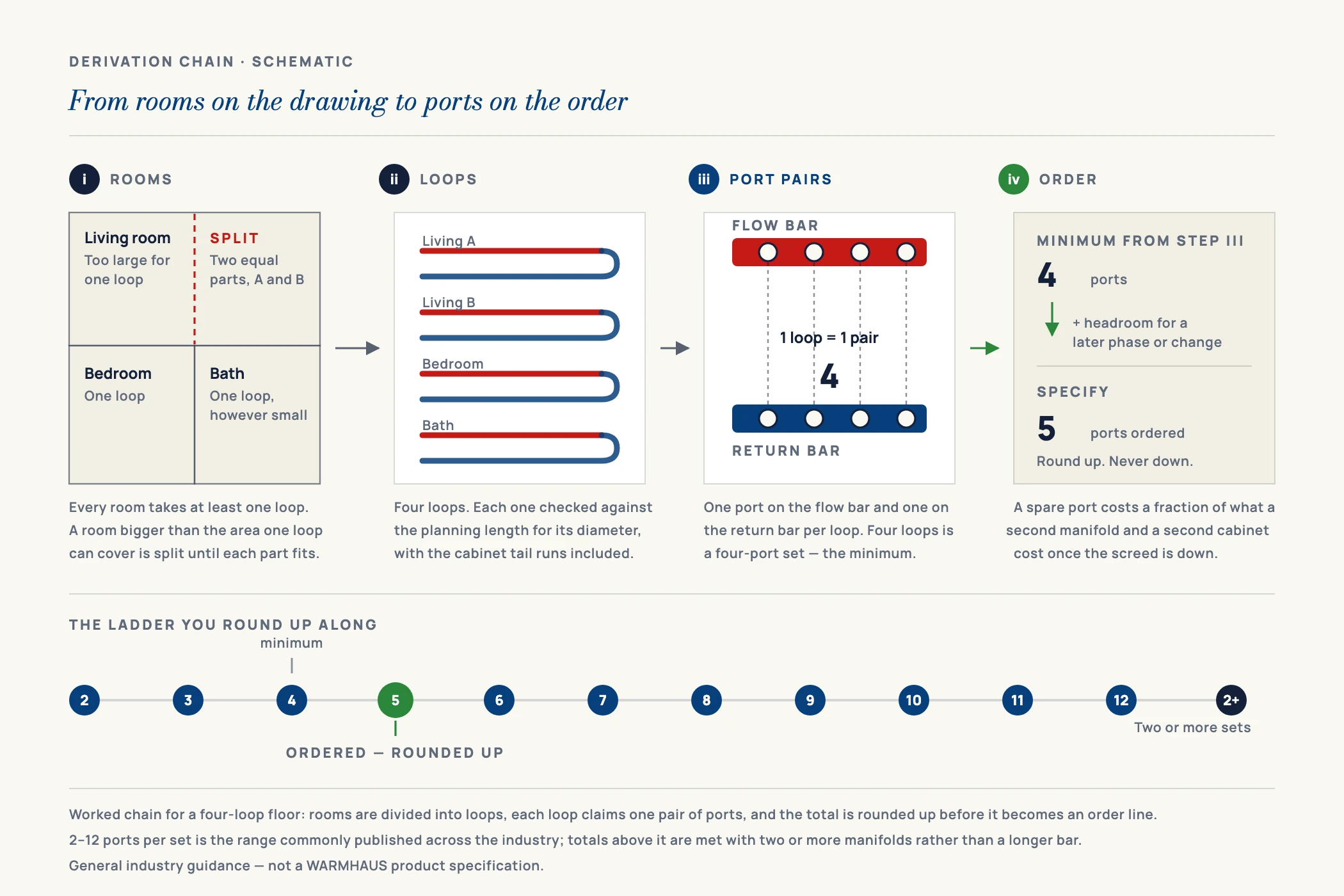
I. Divide the floor into loops, room by room
Work room by room, not building-wide. Small rooms take one loop each; large rooms take several. As a first pass, divide each room’s heated area by the indicative area per loop for your chosen pipe diameter and spacing, then round up. A 34 m² living room on 16 mm pipe at 150 mm spacing is two loops, not one — the single-loop version would exceed the length ceiling.
II. Check every loop against the length ceiling
Add the tail length — the run from the manifold cabinet to the room and back — to the pipe laid inside the room. Tails are where loop-length calculations quietly fail: a room 15 m from the manifold adds roughly 30 m of pipe to that loop before a single metre is laid in the floor. Any loop that breaks the ceiling gets split.
III. Sum the loops and add headroom
The loop total is the minimum port count. Add one spare port where the building is likely to change — a garage conversion, a future extension, a screed area left out of phase one. A spare port costs a fraction of a second manifold and a second cabinet later.
IV. Decide one manifold or several
If the total exceeds the largest available port count, or if the loops would need punishing tail runs to reach one central cabinet, use more than one manifold. Two 6-port manifolds placed near their zones will usually out-perform a single distant twelve-way, because shorter tails leave more of each loop’s length budget for the floor itself. Note that the split decision usually arrives well before the catalogue ceiling does: geometry forces it long before port availability does. Multi-storey buildings almost always take one manifold per floor for the same reason.
IV. Port Count by Property Size — Planning Reference
The table below converts heated area into an indicative port count for early-stage planning and stock forecasting. The arithmetic behind it is explicit: 16 mm pipe at 200 mm centres, which is roughly 20–24 m² of floor per loop from the table above, with the loop band rounded to whole circuits. It is a starting point for a quotation, not a substitute for the loop-by-loop method — a plan with many small rooms needs more ports than area alone suggests, because every room takes at least one loop however small, and tighter spacing at 150 mm centres cuts the area per loop to about 15–18 m² and pushes every row up.
| Heated area | Typical loops | Indicative manifold | Typical application | Note |
|---|---|---|---|---|
| Up to ~24 m² | 1–2 | 2-port | Bathroom, single room retrofit | Minimum practical size |
| ~24–48 m² | 2–3 | 3-port | Small apartment, extension | Add a port if rooms are many and small |
| ~48–72 m² | 3–4 | 4-port | One-bedroom apartment, ground floor | |
| ~72–96 m² | 4–5 | 5-port | Two-bedroom apartment | |
| ~96–120 m² | 5–6 | 6-port | Small house, full floor | Check tail lengths to far rooms |
| ~120–144 m² | 6–7 | 7-port | Family house, one storey | |
| ~144–192 m² | 7–9 | 8- or 9-port | Large single floor, villa storey | Check body bore carries the summed flow |
| ~192–264 m² | 9–12 | 10- to 12-port | Villa floor, light commercial plate | Near the top of the usual catalogue ladder |
| Above ~264 m² | more than 12 | Two or more manifolds | Multi-storey, villa, commercial | Usually one per floor or per zone |
Values are general industry guidance for planning and stock estimation, not a WARMHAUS-specific specification. Area bands are calculated from the ~20–24 m² per loop figure above (16 mm at 200 mm centres) and rounded to whole circuits — the lower loop figure in each row is the count at 24 m² per loop, the higher one the count at 20 m². Loop counts move with pipe diameter, spacing, floor construction, insulation and the room layout. Always size from the project heat-loss calculation and the datasheet of the pipe and manifold in use.
For distributors the middle columns matter more than the first, and the table itself suggests where the volume sits. Map the ladder onto a housing stock: apartments and small house floors of roughly 45 to 120 m² land on 3- to 6-port bodies, and in most residential markets that size band is the bulk of the dwellings being built. The 2-port serves single-room retrofits only, and the 10- and 12-port bodies serve villa floors. That is an argument for holding the middle of the ladder deep and the two ends thin — but it is arithmetic from a floor-area distribution, not a sales statistic, so weight it against the actual dwelling mix in your own market before committing a container. The brass manifold range is worth checking against the port counts your market’s housing stock actually generates.
V. What Else the Manifold Has to Carry
Port count settles the body. Three further decisions ride on it, and each one changes the part number you order.
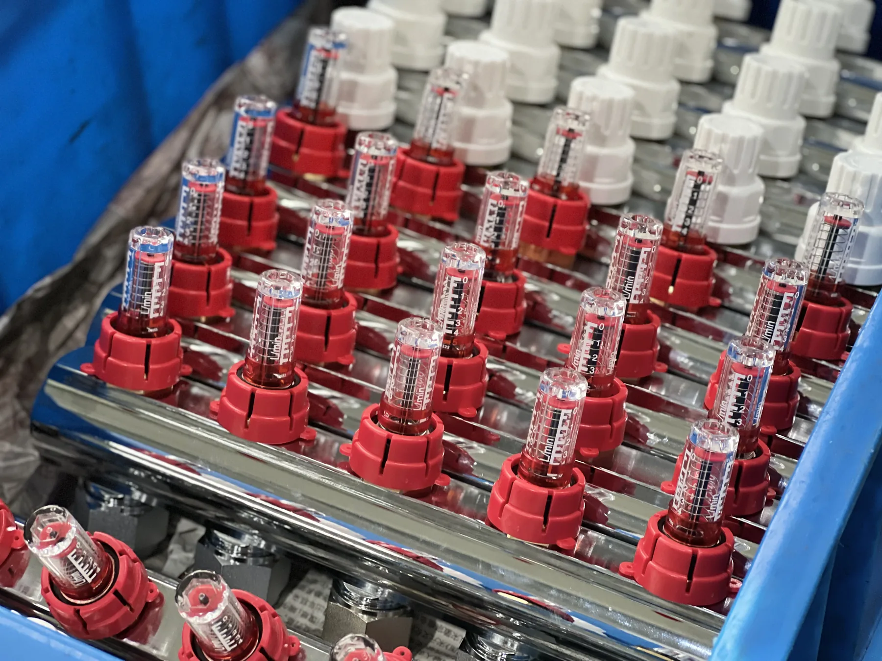
Flow meters. A manifold with flow meters on the ports lets each loop be balanced to a read value rather than by feel, which is what makes unequal loop lengths workable. On a floor where every loop came out within a narrow band, plain balancing valves may be enough; on a mixed floor with a long loop and a short one, flow meters stop the argument. The decision is per manifold, not per port, so it is made once the loop schedule exists.
Actuator provision. If any loop is to be controlled by a room thermostat, the return bar needs actuator-ready valve inserts on those ports. Retrofitting them later means draining the manifold. Count the thermostatically-controlled zones at the same time as you count the loops, because the two numbers are usually different — several loops may sit under a single zone.
Adapters matched to the pipe. Every loop needs a compression adapter matched to its pipe outside diameter and wall. This is where a mixed bill of materials bites: adapters ordered against one supplier’s pipe dimensions and used on another’s are a slow leak waiting for the screed to go down. Ordering the PEX pipe and the adapters from the same manufacturer removes the tolerance question from the site. The same logic runs through the underfloor heating system as a whole — pipe, manifold, actuator and thermostat sized as one set.
VI. Six Sizing Mistakes That Cost Money
These are the recurring ones — the errors that turn into a second delivery, a second cabinet, or a floor that never balances.
Sizing by area alone
Area-to-port tables are planning tools. A floor plan of many small rooms needs a port for each of them regardless of area. Fix: count loops room by room first, then use the area table only as a sanity check.
Forgetting the tails
The run from cabinet to room and back is part of the loop and eats the length budget before any pipe is laid in the floor. Fix: add both tail runs to every loop before checking it against the length ceiling.
Loops of wildly unequal length on one manifold
The short circuit takes the flow and the long one starves; no amount of valve adjustment fully compensates. Fix: split large rooms so loop lengths on a manifold sit in a narrow band.
Zero headroom
Ordering exactly the ports counted leaves nothing for a late change or a phase-two area. Fix: specify one spare port where any future extension is plausible.
One central manifold for a whole building
Long tails to distant rooms consume the loop-length budget and force extra loops that would not otherwise be needed. Fix: place manifolds near their zones — typically one per floor.
Adapter thread and pipe diameter not checked together
The correct port count with the wrong adapter for the pipe stops the installation. Fix: specify pipe outside diameter and adapter on the same line of the order, and source both together.
VII. Sizing a Container, Not Just a Floor
An importer sizes differently from an installer. The installer needs the right manifold for one floor; the importer needs a port-count mix covering a market’s typical housing stock without dead stock at the extremes. The area table above is the starting distribution — weight the ladder towards the dwelling sizes your market actually builds, and stock adapters against the pipe diameters it actually installs.
This is where sourcing the whole set from one manufacturer changes the arithmetic. WARMHAUS is a manufacturer of PPR, PEX and brass piping systems — not a trading company. The extrusion, injection-moulding and machining lines are our own, so manifold bodies, adapters and pipe are held to one internal standard instead of averaged across three suppliers. Manifolds are machined from brass in-house; the PEX pipe that feeds them is extruded in the same house. Manufacturing since 1993, ISO 9001 / ISO 14001 / ISO 45001 certified, EU CE marked and SGS tested — certificate documents available on request for tender and customs files. And because there is no MOQ, a first order can carry a spread of port counts in small quantities to find where demand actually sits, instead of committing a container to a guess. Standard lead time is 45 days, planned into production slots.
Send us the port-count mix, the pipe diameters your market installs and the adapter thread you need, and we will come back with the manifold specifications and terms. Request the manifold sizing and specification pack — port dimensions, adapter options, flow-meter versions and the matching pipe range. Pricing and certificate documents: available on request.