An underfloor heating manifold does one job nothing else in the system can do: it takes a single supply of warm water and splits it into several independent loops, each with its own measured flow rate, then collects them back into a single return. Every other part — flow meters, actuators, mixing group, isolation valves — exists to control or protect that one split. Understand the split and the assembly stops looking like a rack of brass and starts reading as a sequence you can commission, fault-find and specify.
What follows traces the water from heat source to screed and back, and explains why a loop that is plumbed correctly can still run cold if it has never been balanced. Figures below are general industry guidance, not a WARMHAUS specification — confirm them against the datasheet of the manifold, pipe and controls you are installing.
I. What a Manifold Is — and What It Is Not
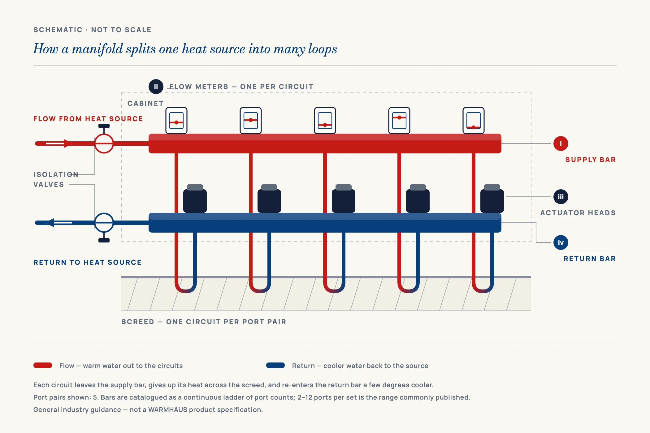
Physically, a manifold is a pair of horizontal bars mounted one above the other on a bracket, usually inside a recessed or surface cabinet. One bar is the flow bar, the other the return bar. On many designs the upper bar is the flow bar and the lower the return, but the arrangement is not standardised and is reversed on some models — and because it determines which bar carries the flow meters and which carries the inserts the actuators screw onto, getting it wrong means rewiring. Identify the bars from the datasheet and the body markings of the model in front of you, not from their position. Each bar carries a row of identical outlets on a fixed centre distance, and each outlet accepts a compression adaptor terminating one end of a floor loop. Two legs of pipe therefore leave every port: one going out into the screed, one coming back.
What it is not is a tee arrangement. A tee splits flow in whatever proportion the downstream resistances dictate; a manifold splits it in the proportion you dictate, because every port carries an adjustable restriction. Loop lengths are never equal — a bathroom loop might be 40 m and a living-room loop 95 m — and water, given a free choice, takes the short loop every time. Without per-port adjustment the short loop runs hot, the long one cold, and raising flow temperature only makes the hot room hotter.
A tee divides water by accident. A manifold divides it on purpose — that single difference is what makes a floor commissionable.
Nor is it a heat source: in its basic form it neither generates heat nor lowers temperature. Because boilers deliver water far hotter than a screed floor can safely accept, a manifold serving a floor is normally paired with a pump and mixing group — a decision made upstream, and covered in our guide to the complete underfloor heating system.
II. Follow the Water: the Flow Path Step by Step
Every component you will later have to specify, price or troubleshoot sits somewhere on this path.
I. Arrival at the flow bar
Warm water enters through the main isolation valve — often a ball valve, sometimes with a thermometer in the handle so supply temperature is readable without instruments. If a mixing group is fitted, the water arrives already blended and pumped to target. The bar is a pressurised chamber: water fills its whole length and presents equal pressure at every outlet.
II. Metering at each flow port
At each flow-bar outlet sits a flow meter — the clear tube with a float scaled in litres per minute, showing what that loop is drawing. On most designs the meter body doubles as the adjusting device: turning its collar opens or closes a restriction and the float responds. It is the most useful diagnostic on the assembly, turning an invisible hydraulic problem into something readable at a glance.
III. Out into the screed and back
The metered water travels the full loop buried in the screed, gives up its heat to the slab, and returns cooler. The difference between what went out and what came back — the loop delta T — is the real measure of whether that loop is doing its job. Loop pipe is normally oxygen-barrier PEX or PE-RT, and its outside diameter must match the compression adaptors on the ports.
IV. Return, throttling and actuation
The loop terminates on the return bar, whose ports usually carry thermostatic valve inserts — spring-loaded stems a room thermostat drives shut through an electrothermal actuator. At setpoint the actuator closes the insert and that loop stops circulating while its neighbours carry on; manual caps sit on the inserts where no zone control is fitted. Worth remembering: flow side meters and balances, return side switches on and off.
V. Collection and exit
All returning loops merge in the return bar and leave through the second isolation valve toward the heat source. At the far end of both bars sit the fill/drain cocks and automatic air vents. An air pocket blocks circulation as effectively as a closed valve — which is why filling and venting is the first act of commissioning.
III. Manifold Component Reference Table
Keep this table open when reading a quotation or checking a delivery against a packing list. Configuration varies by manufacturer and project — treat “typical supply” as orientation, not a purchase specification.
| Component | Where it sits | What it does | Typical supply |
|---|---|---|---|
| Flow bar (supply bar) | Upper bar on many models — verify per datasheet | Distributes water at equal pressure to every outgoing loop | Standard |
| Return bar (collector) | Lower bar on many models — verify per datasheet | Collects all loops into a single return to the heat source | Standard |
| Flow meter | Flow-bar ports | Displays and adjusts each loop’s flow in l/min — the balancing device | Standard or optional by model |
| Thermostatic valve insert | Return-bar ports | Spring-loaded stem opening or closing one loop; capped if no zone control | Standard |
| Electrothermal actuator | Screws onto return inserts | Driven by the room thermostat; closes the loop at setpoint | Optional per zone |
| Main isolation ball valves | Both bar ends | Shut the manifold off for service without draining the building | Standard or optional by model |
| Automatic air vent | End of each bar | Releases trapped air that would stall circulation | Standard |
| Fill / drain cock | End of each bar | Filling, flushing and draining during commissioning and service | Standard |
| Compression adaptor (eurocone) | Every port | Terminates the loop pipe; must match pipe outside diameter and wall | Ordered to pipe size |
| Thermometer | Isolation valves or bar ends | Reads flow and return temperature for commissioning | Optional |
| Pump and mixing group | Upstream of the flow bar | Blends down to floor-safe flow temperature and circulates the loops | Optional, design-dependent |
| Mounting bracket set | Behind the bars | Carries the assembly and isolates structural vibration | Standard |
| Cabinet | Encloses the assembly | Recessed or surface enclosure giving protected access | Optional |
Component list is general industry guidance, not a WARMHAUS-specific specification. Which items ship as standard and which are ordered separately differs by model and by project; always confirm against the datasheet and packing specification of the manifold you are ordering.
Port count follows loop count, not room count. Across the market, brass manifold bodies are commonly catalogued from 2 to 12 ports per set as general industry guidance; how to convert a floor layout into a port count is worked through in our underfloor heating manifold sizing guide. For the manifold range itself, request the manifold specification sheet and port configuration table for dimensions, centre distances and flow-meter options in the size you are quoting.
IV. Balancing: the Part Everyone Skips
A manifold that is installed but not balanced works at a fraction of its value. Balancing means setting each flow meter so every loop receives the flow its length and its room require, not the flow the hydraulics hand it by default. One room never warming while another overheats on the same floor is almost always a balance fault, not a capacity fault.
Longer loops carry more resistance, so at equal port settings they draw less water; to compensate, throttle the short loops back until the long ones rise to their design flow. That figure comes from each room’s heat loss calculation converted into a flow rate at the design delta T. As general orientation, residential floor loops are frequently designed around a flow-to-return difference in the region of 5–10 K, with flow temperatures well below those used for radiators — but actual values come from the project’s own calculation, not a rule of thumb.
Loops never balanced at all
Every meter left fully open at handover. Short loops take the water, long loops run cold, and the occupant compensates by raising flow temperature — more energy, same cold room. Fix: balance to the design flow per loop before handover and record the settings.
Air left in the loops
An air pocket stops circulation completely, and the float sits at or near zero however far the port is opened. Fix: fill and vent loop by loop with the others isolated, then re-check every float.
Loop lengths wildly unequal
When one loop is several times another, balancing cannot rescue it — the adjustment range is not infinite. Fix: resolve it at design stage by splitting long circuits and keeping lengths within a comparable band.
Actuators fitted the wrong way round
Actuators belong on the thermostatic inserts, not on the flow meters — mounted on the metering side they defeat the balancing function and confuse commissioning. Because which bar carries the inserts varies between models, position is not a safe guide. Fix: identify the insert bar from the datasheet and body markings before wiring, not from whether it sits on top.
Flow temperature set as a substitute for balancing
Raising the mixing group setpoint to force heat into a starved loop overheats every other zone and risks exceeding the floor covering’s limit. Fix: balance first, then set flow temperature to design.
Settings not recorded at handover
Six months later nobody knows whether a meter was tampered with or always set that way. Fix: log the final flow rate for every port and leave a copy in the cabinet.
The physical sequence of bringing the assembly into service — mounting, pipe termination, pressure test and fill — is set out in our underfloor heating manifold installation guide.
V. Why Manifolds Are Made in Brass
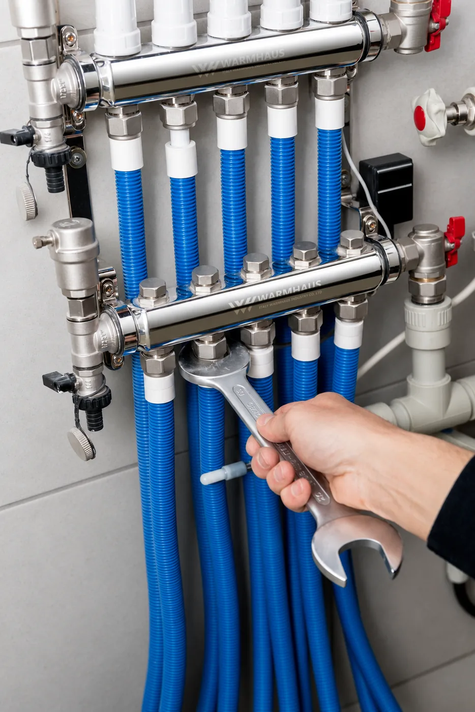
Almost every manifold you will handle is brass, because the component must do several awkward things at once: hold system pressure for decades, seal reliably across a dozen machined faces and threaded ports, and stay dimensionally stable through repeated thermal cycling. Brass bar stock machines cleanly, takes a fine thread and holds those tolerances — which is why the bars, valve bodies and eurocone ports are cut from it rather than moulded. Stainless steel manifolds are common in some markets; that choice is a genuine engineering and commercial decision rather than a settled one.
Corrosion resistance is a separate question from machinability, and one worth putting precisely. Dezincification resistance is not a property that brass carries automatically. It depends on the specific alloy composition and, where required, on a dezincification-resistant grade or an appropriate metallurgical treatment — and some markets and water qualities make a DZR grade a specification requirement rather than an option. Treat “brass” as a family, not an assurance: as general industry guidance, ask which alloy is specified for the product family you are buying, and confirm the dezincification requirement against the destination market’s rules and the datasheet for the actual part. Our note on dezincification in brass fittings sets out where it matters and how it is specified.
What matters more in practice than the headline material is the machining: port centre distances consistent bar to bar, sealing faces cut cleanly, and threads that let an insert or actuator seat without being forced. WARMHAUS machines brass manifolds and manifold bodies on its own lines from 57-3 and CW617 brass, so port geometry is held to one internal standard rather than averaged across outside suppliers. Which alloy applies to a given item, and what that means for the corrosion requirement above, is confirmed per product against the alloy certificate.
VI. Specifying a Manifold You Can Actually Commission
The questions that decide whether a floor commissions cleanly are narrow and practical. Does the port count match the loop count, with a spare if the layout may change? Do the compression adaptors match the pipe outside diameter? Are flow meters fitted on the flow side, so the installer can balance rather than guess? Will the cabinet leave clearance in front of the meters once the wall is closed up? Do the actuator threads match your controls?
WARMHAUS is a manufacturer of PPR, PEX and brass piping systems — not a trading company. The extrusion, injection-moulding and machining lines are our own, so the manifold, loop pipe, actuators and thermostats come from one source with matched threads and dimensions, instead of from four suppliers whose tolerances were never designed to meet. Manufacturing since 1993, ISO 9001 / ISO 14001 / ISO 45001 certified, EU CE marked and SGS tested, with no MOQ and a standard lead time of 45 days — so a distributor can trial a full configuration before committing to volume. Certificate documents, dimensional drawings and pressure ratings: available on request.