Most incomplete underfloor heating deliveries are not caused by a missing manifold. They are caused by a missing end cap, bracket, air vent or adaptor — a small part that stops a whole floor from being commissioned. An underfloor heating manifold is sold as one line on a proforma, but it functions as an assembly of ten to fifteen distinct components, several of which most suppliers quote separately. This article lists every part, states how many of each you need as a function of port count, and separates what normally ships in the box from what you have to add to the order yourself.
It is written for the person building the purchase order rather than the person holding the spanner: importers pricing a first container, distributors setting up a stock list, and contractors checking a quotation against a floor plan. For the installation sequence instead — mounting, pressure testing, balancing and wiring — see the companion guide on how to install an underfloor heating manifold. Here we stay on the parts.
I. What Counts as “the Manifold” — and What Does Not
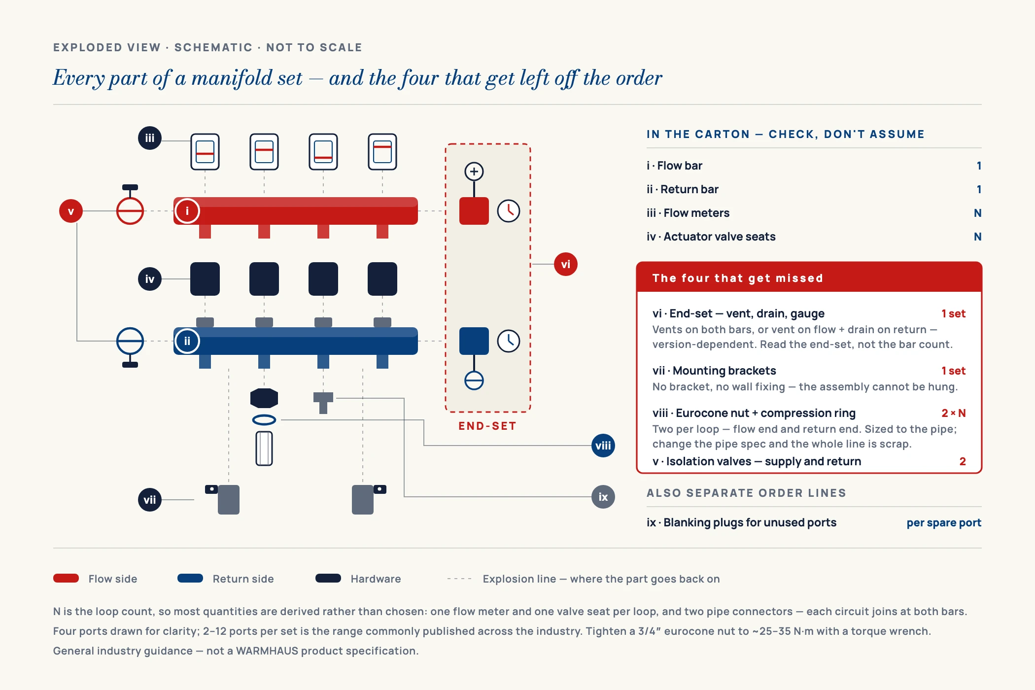
The manifold proper is two horizontal bars mounted one above the other, normally machined from brass. The upper bar is the flow bar: it takes heated water from the heat source out to each floor loop. The lower bar is the return bar: it collects the cooled water coming back. Every loop occupies one outlet on each bar, which is why a manifold is described by its port count — a 6-port manifold serves six heating circuits, using six outlets on the flow bar and six on the return bar.
Ports are not a size. A port is a heating loop — count the circuits on the floor plan and the manifold specifies itself.
Around those two bars sits everything else: the devices that measure flow, the devices that open and close each circuit, the valves that isolate the assembly, the fittings that connect the pipe, and the brackets that hold it on a wall. Some are pre-assembled onto the bars at the factory, some are supplied loose in the same carton, and some are separate order lines entirely — and the boundary moves from supplier to supplier, which is why quotations are hard to compare. Do not assume: read the list below against whatever specification you have been sent, and mark each row as included, extra, or missing.
II. Underfloor Heating Manifold Parts — the Full List
The table below is the complete component set for a standard hydronic underfloor heating manifold assembly, with a quantity rule for each part and a note on whether it typically ships with the manifold or is ordered separately. N is the number of loops, which equals the port count.
| Component | Function | Typical quantity | Usually supplied |
|---|---|---|---|
| Flow bar | Distributes heated water from the heat source out to each loop | 1 per manifold | With the manifold |
| Return bar | Collects cooled water returning from each loop | 1 per manifold | With the manifold |
| Flow meters (flow gauges) | Display and set the flow rate of each circuit — the tool used to balance the system | N (one per loop) | With the manifold on flow-meter versions |
| Actuator valve seats | The valve on each return outlet that the electrothermal actuator screws onto | N (one per loop) | With the manifold |
| Electrothermal actuators | Open or close one loop on demand from the room thermostat | N, or one per zone if loops are grouped | Ordered separately |
| Room thermostats | Call for heat per room or zone and drive the actuators | 1 per controlled zone | Ordered separately |
| Isolation / ball valves | Shut the whole manifold off from supply and return for service | 2 (one flow, one return) | Often a separate order line |
| End caps / end pieces | Close the far end of each bar; carry the vent and drain ports | 2 (one per bar) | With the manifold |
| Automatic air vents | Purge trapped air from the high point of the assembly | Version-dependent: commonly 1–2 per manifold. Some end-sets carry a vent on each bar; on others the vent sits on the flow bar only and the return bar end piece carries a drain | Part of the end-set — check the end-set, not the bar count |
| Drain / fill valves | Fill, flush and drain the loops during commissioning and service | Version-dependent: commonly 1–2 per manifold, often paired with the vents in a combined vent-and-drain end-piece set | Part of the end-set — check the end-set, not the bar count |
| Mounting brackets | Fix the assembly to the wall or into a cabinet, level and clear of the floor | 1 set (2 brackets) | With the manifold |
| Compression / insert adaptors | Connect each PEX loop to a manifold outlet | 2 × N (supply and return per loop) | Ordered separately by pipe size |
| Temperature gauges | Read flow and return temperature to confirm the floor is in range | 1–2 per manifold | Version-dependent |
| Pump / mixing group | Blends hot source water down to floor temperature and circulates it | 1 per manifold where required | Ordered separately |
| Manifold cabinet | Recessed or surface enclosure protecting the assembly | 1 per manifold, sized to port count | Ordered separately |
| Wiring centre | Common terminal point between thermostats, actuators and the heat source | 1 per system | Ordered separately |
Quantities and inclusions are general industry guidance, not a WARMHAUS-specific specification. What ships in the carton differs by manifold version and by supplier — always confirm the scope of supply against the datasheet and packing list of the manifold you are actually buying, and against the technical data of the pipe and controls you pair with it.
The end-set rows deserve a closer look, because they are the ones most often read as a fixed rule when they are not. It is convenient to say “one vent and one drain per bar”, and on many manifolds that is what arrives. But the arrangement is genuinely version-dependent: some end-sets put an automatic vent on each bar; others put the vent on the flow bar — the natural high point for air to collect — and give the return bar a drain-and-fill cock only; others again supply a single combined vent-plus-drain end piece per bar as one part number. All three are normal. What matters commercially is not which arrangement you prefer but that you count the end-set as one line and read what is in it, rather than assuming a quantity of two and discovering on site that the assembly cannot be vented or cannot be drained.
Two further rows cause most of the shortfalls. The outlets are threaded, so the connection to the floor pipe is made by an adaptor sized to the pipe you are running — two per loop, not one. And manifolds ship with the valve seats but rarely with the actuator heads, because the head has to match the control voltage and the thermostat; both sit in the underfloor heating controls range.
III. How to Turn a Floor Plan Into a Parts Count
The whole bill of materials derives from one number — the loop count — so establishing that number correctly is the entire exercise. Work through it in this order.
Count the circuits, not the rooms
Each heated area needs at least one loop, and a large open-plan area is normally split into two or more circuits so no loop exceeds the maximum length the designer allows. The circuit count on the heating layout — not the room count on the architectural plan — is your N.
Round the port count up, never down
If the plan gives five loops, specify a six-port manifold. The spare outlet is capped now and used later when a conservatory, garage or extension is added, and it costs far less than a second manifold and a second supply run.
Split by floor, not by building
A single very large manifold is harder to balance and forces long loop runs back to one point. Standard practice is one manifold per floor or wing, each with its own isolation valves — so a two-storey house is usually two smaller assemblies.
Count actuators by zone, not always by loop
Where several loops serve one thermostatically controlled area, they can share a zone and switch together. That reduces the actuator and thermostat count below N — but only if the zoning is decided before the order, because the wiring centre is sized for it.
Fix the pipe size before the adaptors
Adaptors are ordered against the outside diameter and wall of the floor pipe. Change the pipe specification afterwards and the whole adaptor line is scrap — the most common reason a manifold shipment cannot be connected on arrival.
Size the cabinet against the assembled width
The enclosure has to clear the assembled manifold including the flow meters, the actuator heads and any pump group — not the bare bar length. Cabinet sizes step up with port count, so specify it from the final assembly rather than from the manifold model number alone.
IV. The Parts Most Often Missing From a Quotation
A quotation is not a bill of materials. Four components sit outside the headline manifold price often enough to be worth checking every time. Adaptors — a quotation listing a manifold and a pipe coil but no adaptors describes parts that cannot be joined. Isolation valves — frequently assumed to be part of the manifold and frequently not; without them, servicing one manifold means draining the system. The pump or mixing group — required wherever the heat source delivers water hotter than the floor construction allows, which makes it a design decision rather than a default inclusion. The cabinet and wiring centre — both sized from the rest of the assembly, both usually remembered only when the installer arrives.
The practical defence is to quote from the parts table above rather than from a supplier’s product page, and to ask one direct question of every line: is this included, or is this extra? A supplier that answers that line by line is a supplier whose container arrives complete. If you are assembling a first order, request the manifold and controls specification sheets from our technical office and we will mark each component as included or separate against your port count.
V. Why the Parts Should Come From One Manufacturer
Every interface in the list above is a place where two parts have to fit each other: the actuator head onto the valve seat, the adaptor onto the outlet, the thermostat signal into the actuator, the assembly into the cabinet. When those parts come from four suppliers, each interface becomes a tolerance question — and the answer only arrives when the crate is opened on site.
WARMHAUS builds the manifold, the controls and the pipe. We are a manufacturer of PPR, PEX and brass piping systems — not a trading company — and the machining, extrusion and injection-moulding lines are our own. That is why the brass underfloor heating manifold range is dimensioned around the same PEX pipe and electrothermal actuators we produce, and why the same machined body also appears in the wider brass manifold line used for potable water distribution. One drawing set, one internal standard, one packing list. Port counts across the industry commonly run from 2 to 12 loops per manifold as general industry guidance — how to arrive at the right number for a given floor is worked through in the manifold sizing guide; confirm the counts available in any specific range against the current datasheet.
For a distributor that means a shelf answering a whole enquiry instead of half of one — manifold, actuators, thermostats, pipe and adaptors on a single account across the complete product range, with no MOQ, so a first order can be a mixed pallet rather than a container of one item. Manufacturing since 1993, ISO 9001 / ISO 14001 / ISO 45001 certified, EU CE marked and SGS tested, with certification files supplied for tender and customs paperwork. Standard lead time 45 days from order confirmation, planned into production slots. Port counts, dimensions, certificate documents and pricing: available on request.