Ball Valve Handle Turns but Water Still Flows: What Does It Prove?
A ball-valve handle turning to the closed-looking position does not, by itself, prove that the water is isolated. A loose handle, damaged stem or failed connection between stem and ball can separate the visible lever movement from the internal movement. Continuing flow can also have other explanations, including an alternative feed, a leaking seat or a finite quantity of water draining from the downstream system.
If isolation is needed before opening pipework or removing equipment, treat uncertain shutoff as unproved. Obtain an independent upstream isolation and verify the relevant system has been made safe under its procedure before dismantling. Do not remove a stem, packing assembly or union from a live valve to find out what happened.
Key takeaways
- The lever is an indicator connected through a mechanical drive chain.
- Free movement can indicate lost engagement; it is not a reliable sign that the ball moved.
- Continuing flow does not identify one failure without checking the water path.
- A finite drain-down and a continuing replenished supply are different observations.
- Isolation must be verified for the work, rather than inferred from lever angle.
- Repairable parts and replacement decisions depend on the exact valve model.
Follow the movement from handle to ball
In normal operation the handle drives a stem, and the stem turns the ball. The visible handle is only the first part of that chain. A familiar lever position is useful when the assembly is intact and correctly configured. Once the handle turns unusually freely, slips or no longer agrees with the observed result, the normal visual inference becomes unreliable.
The Asahi Type-21 item 1609015 manufacturer troubleshooting information identifies damaged stems, loss of handle engagement and damaged stem/ball engagement as possible reasons for a handle rotating too freely. This is evidence that those are distinct mechanical failure paths in the named product. It is not a spare-parts or disassembly instruction for a different brass or PP-R valve.
The important observation is therefore not simply that the handle went through a quarter turn. Record whether the handle moved the expected amount, whether it moved with the stem and whether the intended water path actually stopped. Do not force a stiff valve or use a longer lever to turn uncertainty into an apparent closed position.
| Observation | Possible explanation | Conclusion for isolation |
|---|---|---|
| Handle moves freely but the expected result does not follow | Handle engagement or internal drive may be damaged. | Shutoff remains unproved. |
| Handle appears closed and downstream water continues | Seat leakage, another feed, misidentified valve or drive failure remains possible. | Identify the flow path; lever angle alone cannot resolve it. |
| A small quantity leaves an isolated downstream section and then stops | Finite retained water may be draining. | Still verify the safe state required for the work; one outlet observation is not a complete isolation procedure. |
Separate remaining water from a renewed supply
A downstream line or appliance can contain water after its supply has been shut. That remaining volume is not the same observation as a supply that continues to replenish the outlet. However, do not set a universal waiting period or quantity to distinguish them: the connected equipment, branch lengths, storage, elevation and possible alternative feeds vary.
Use the system drawing or an informed inspection to establish what the valve controls. A mixer, recirculation connection, storage vessel or another supply path may make the observed outlet a poor single test point. If the water path is unknown, record that missing input and resolve it before selecting a failed component.
This also explains why an outlet that stops momentarily does not settle every safety question. The work may expose a different section or stored energy. The responsible person must verify the isolation appropriate to that work, rather than treating any convenient open tap as a universal test.
Keep a failed drive separate from a leaking seat
A damaged drive and a damaged sealing interface can both leave water passing, but the mechanical evidence differs. A loose or disconnected handle may fail to move the ball. A valve whose ball reaches its intended position can still pass water if the sealing interface is damaged or obstructed. The symptom “still flowing” cannot choose between those explanations on its own.
The cited Asahi item 1609015 product information separately lists causes for a valve passing fluid when fully closed and causes for a handle rotating too freely. That separation is useful for organising an investigation. It does not establish which cause is present in the valve on your site, or justify opening it while it retains pressure.
A replacement handle is therefore not automatically a complete repair. Its fit, stop arrangement and condition of the mating drive matter. Replacing a visible part while leaving a damaged stem or internal engagement unresolved can restore the appearance of normal operation without restoring reliable shutoff.
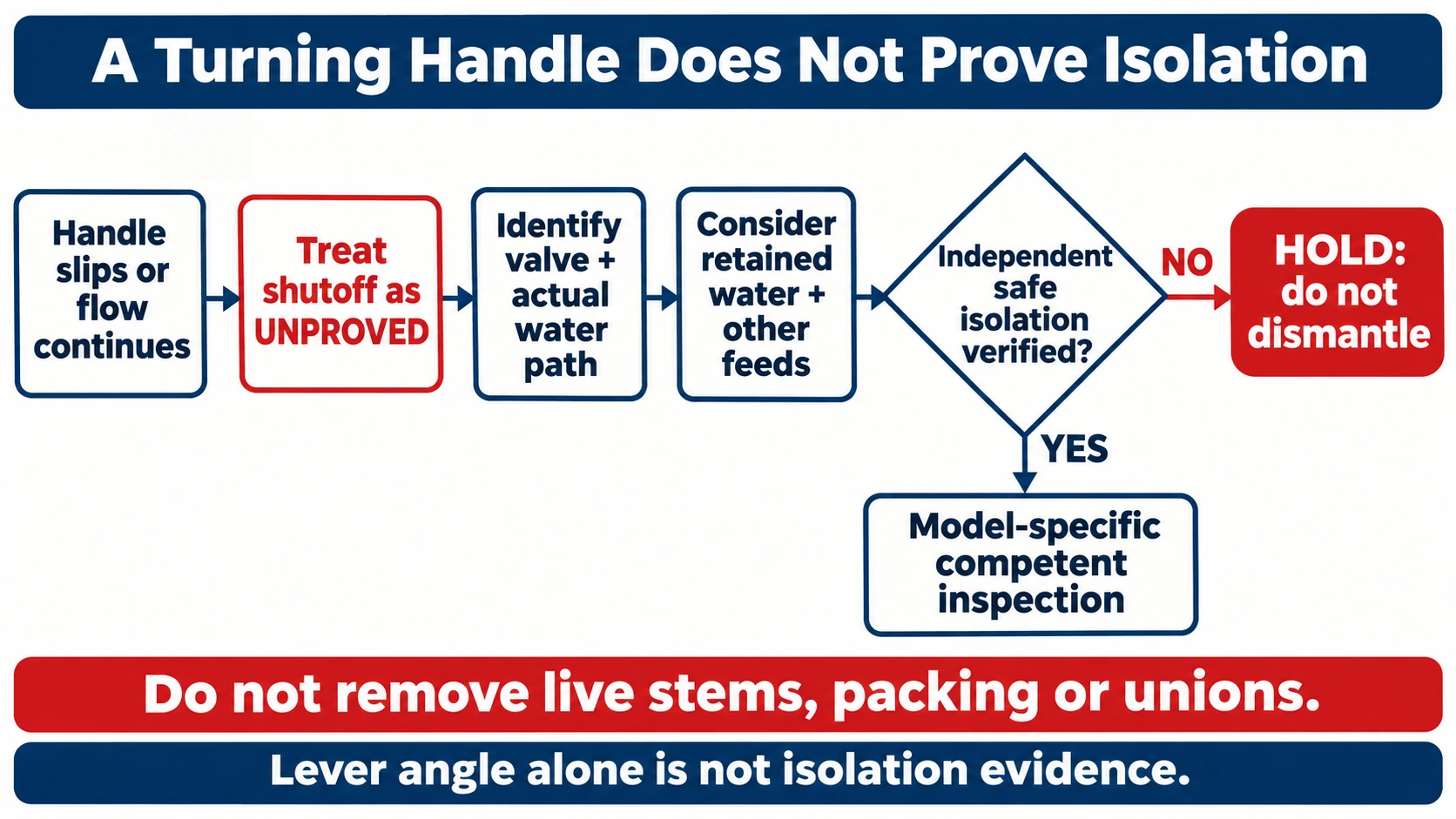
Review sequence shown in the flowchart
- Treat uncertain isolation as unproved
- Identify valve and water path
- Distinguish retained water and other feeds
- Establish independent safe isolation before invasive inspection
- Apply model-specific repair or replacement direction
Set the stop point before dismantling
If the suspect valve is the only proposed isolation, the investigation has reached a limit. Arrange an independent upstream isolation, account for other feeds and stored energy, and follow the site’s verification procedure. Where this cannot be established, keep the work on hold and involve the competent operator or installer.
A “blowout-proof” stem designation should not be interpreted as permission to remove live parts. Nor does the absence of an external drip prove that the downstream line is isolated. External containment, internal shutoff and safe disassembly are three separate questions.
- Identify the exact valve and the section it is intended to isolate.
- Record the handle behaviour and continuing flow without forcing the mechanism.
- Check for alternative feeds and retained water through the responsible system review.
- Establish independent isolation and the required verified safe state before invasive inspection.
- Apply the manufacturer’s model-specific repair or replacement direction.
Two practical decisions
Illustrative case A: the loose lever moves, but the stem does not visibly follow. The finding supports a handle-drive problem; it does not prove that the stem and ball beyond it are sound. The immediate work decision is to reject the lever position as isolation evidence. After independent isolation, the correct handle, engagement and any further damage can be assessed using the valve’s instructions.
Illustrative case B: the lever and stem move together, but a downstream outlet has continuing replenished flow. A simple loose-handle explanation is less persuasive. Check that this is the intended isolating valve and whether another path supplies the outlet. If the path is confirmed, the valve’s internal shutoff needs investigation. The action remains a safe inspection or replacement decision, not extra handle torque.
Change case B so that only a finite quantity drains and the system has no alternative feed. That supports a different explanation of the water observation, but it still does not substitute for the isolation verification required before the planned work.
Specify a replacement from the duty
Once replacement is the documented decision, identify the service, actual connection, dimensions, pressure and temperature duty, accessibility and maintenance arrangement. Match those against a confirmed product, rather than ordering from the handle colour or the nominal size alone. A valve’s ability to fit the pipe is not the whole selection.
For available WARMHAUS valve options, use the brass-valve specification discussion to organise an enquiry. Confirm the current model’s actual data and service provisions directly. This article does not establish that every valve has replaceable stems or that a third-party repair kit fits a WARMHAUS assembly.
| Observation | Interpretation limit | Work decision |
|---|---|---|
| Lever moves; stem does not follow | A drive problem is suspected; internal condition remains unproved | Reject lever angle as isolation evidence |
| Lever and stem move; replenished flow continues | Another feed or a shutoff problem remains possible | Investigate the water path under the safe procedure |
| Finite drainage; no alternative feed established | Retained water is a possible explanation | Still verify the isolation required for the planned work |
Conclusion
A turning handle is evidence of handle movement. Reliable isolation needs the drive, sealing function and actual water path to be established. Separate mechanical disengagement, seat leakage, other feeds and retained water before choosing a remedy, and establish an independent safe isolation before dismantling the suspect component.
Frequently asked questions
Does a perpendicular lever prove a ball valve is closed?
It is a normal indication for an intact, correctly configured assembly. It does not prove isolation when the handle or internal drive is damaged.
Can I tighten the handle and continue working?
Only the actual model’s inspection and repair decision can establish that remedy. Restoring the lever position alone does not verify internal shutoff.
Why can water continue after a valve closes?
Possibilities include retained downstream water, another feed, the wrong valve or failed internal shutoff. The flow path and observation must distinguish them.
Can I remove the stem to inspect it?
Do not dismantle a live or uncertainly isolated valve. Establish the required independent isolation and verified safe state before model-specific inspection.
Written by Justin.