When one room in an underfloor heating system stays cold, the manifold is the first place to look — not the boiler, not the thermostat. Water is lazy: given a choice between a 40 metre loop and a 110 metre loop it takes the short one, and the long circuit ends up with a fraction of its design flow. Balancing throttles the easy loops until every circuit gets the flow rate its floor area requires. It takes flow meters, a calculation you can do on paper, and about an hour of methodical work.
This guide assumes PEX or PERT loops on a brass manifold with flow meters, already mounted, filled, purged and pressure-tested; if not, the manifold installation guide covers mounting and first fill. All figures below are general industry guidance, not WARMHAUS specifications — work to the designer’s schedule and the datasheet of the manifold and pipe you are using.
I. What Balancing Actually Does
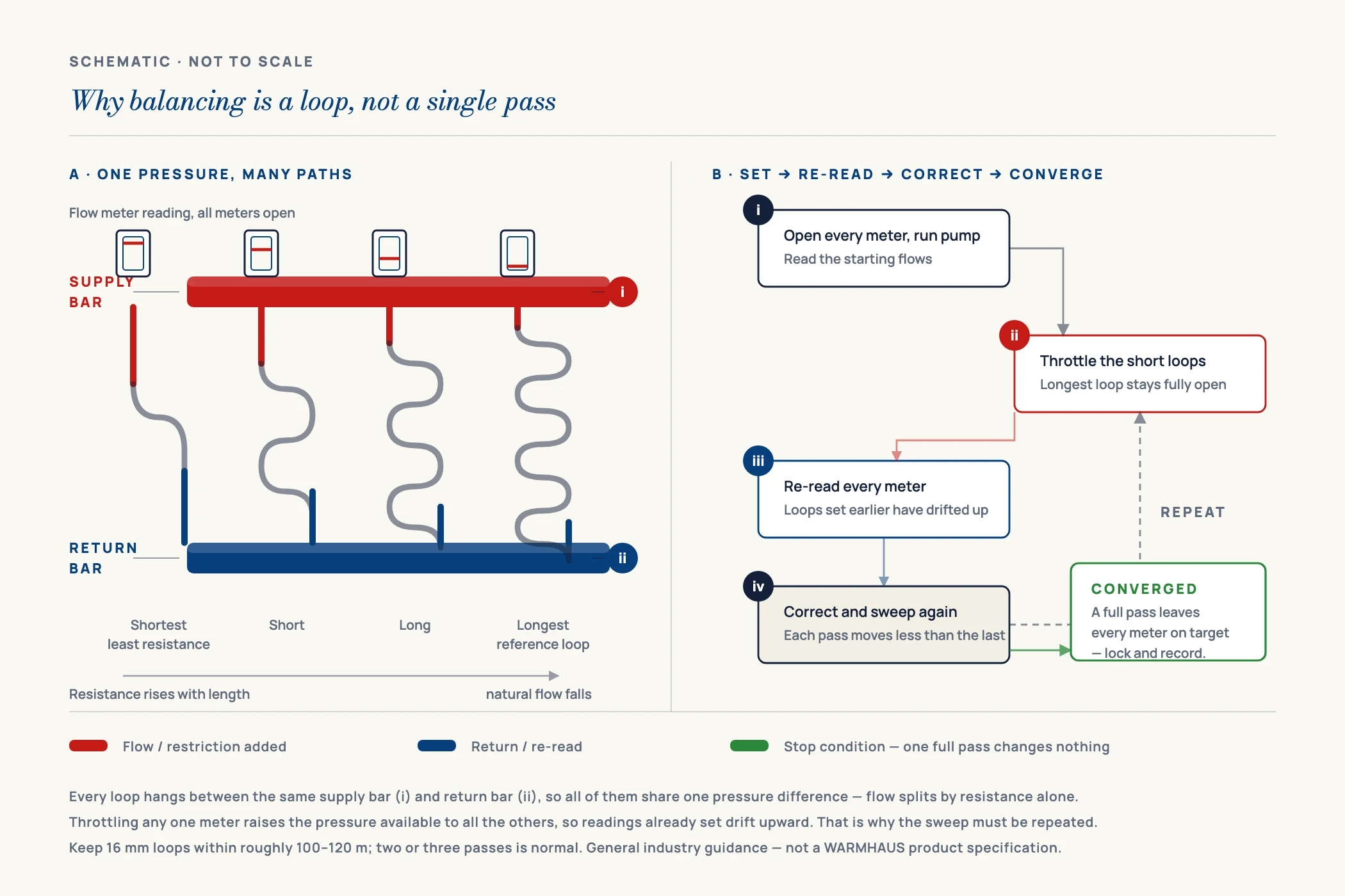
A manifold is a parallel circuit. Every loop leaves the same supply bar and returns to the same return bar at the same pressure, so flow is decided purely by each loop’s own resistance — which rises with pipe length and tight bends, and falls with pipe diameter. A short bathroom loop will swallow two or three times its design flow, while a long living-room loop — the biggest floor area, needing the most heat — gets starved.
An unbalanced manifold does not distribute heat. It distributes it to whichever room the pipework happened to make easiest.
The flow meter on each circuit is a variable restrictor with a graduated sight glass. Screwing it down adds resistance to a loop with too little of its own, forcing the surplus into the loops that need it. Balancing is therefore always closing down the easy loops, never opening the hard ones — and it is iterative, because every adjustment changes the pressure available to the others.
II. Calculate the Flow Rate Each Loop Needs
Before touching a flow meter you need a target number for every circuit. The calculation is a heat balance: the water must carry away exactly the heat the floor above emits, and the temperature it loses doing so is the design temperature difference (ΔT), typically 5–8 K in a residential radiant floor.
Flow (l/min) = Heat output (W) ÷ (ΔT × 69.8)
Heat output is the room’s design demand, or floor area multiplied by the specific output of the floor construction. The constant 69.8 folds in the specific heat capacity of water and the seconds-to-minutes conversion; for litres per hour, multiply by 60. A room emitting 1,400 W at a ΔT of 7 K therefore needs 1,400 ÷ (7 × 69.8) ≈ 2.9 l/min.
Where a room has two loops, split the calculated flow in proportion to loop length, not equally. And because a lower ΔT means higher flow for the same heat, never mix ΔT values across one manifold.
III. Typical Flow Rates by Floor Area and Loop Length
The table below is a sanity check on your calculated numbers — a way to catch an order-of-magnitude error before balancing to the wrong targets. It assumes a screeded residential floor, 16 mm PEX or PERT loops at roughly 150 mm spacing, and a design ΔT in the 5–8 K band.
| Floor area served | Typical loop length | Design output (guide) | Flow at ΔT 5 K | Flow at ΔT 7 K | Flow at ΔT 8 K |
|---|---|---|---|---|---|
| 8 m² | ~55 m | ~480 W | ~1.4 l/min | ~1.0 l/min | ~0.9 l/min |
| 10 m² | ~70 m | ~600 W | ~1.7 l/min | ~1.2 l/min | ~1.1 l/min |
| 12 m² | ~85 m | ~720 W | ~2.1 l/min | ~1.5 l/min | ~1.3 l/min |
| 15 m² | ~105 m | ~900 W | ~2.6 l/min | ~1.8 l/min | ~1.6 l/min |
| 18 m² | ~120 m | ~1,080 W | ~3.1 l/min | ~2.2 l/min | ~1.9 l/min |
| 20 m² | ~135 m | ~1,200 W | ~3.4 l/min | ~2.5 l/min | ~2.1 l/min |
Values are general industry guidance, not a WARMHAUS-specific specification. Loop lengths assume ~150 mm spacing plus a tail run to the manifold. Always confirm against the heating design for the building and the datasheet of the pipe and manifold you are using.
Two structural rules sit behind this table. Keep loop lengths within roughly 100–120 m for 16 mm pipe — beyond that, pressure drop climbs past what a domestic circulator can overcome. And keep loops on one manifold similar in length: a 45 m loop beside a 120 m loop is hard to balance without straining the pump. If the layout forces that spread, split across two manifolds — which is why manifold port counts are chosen at design stage.
IV. How to Balance the Manifold — Step by Step
Work in this order — skipping the preparation steps is what makes balancing take three attempts.
I. Purge every loop and confirm the system is air-free
Air in a circuit reads as low flow and will send you chasing a problem that does not exist. Flush the loops one at a time with the others closed, until the water runs clear and silent, then top up pressure and open the automatic air vents on the manifold bars.
II. Open all flow meters fully and start the circulator
Set every circuit wide open, run the pump at design speed, and open all return valves. Let the readings settle, then note what each meter shows — that list tells you immediately which loops are the greedy ones.
III. Set the longest loop first, then work down
The longest circuit is the reference: already fully open, it cannot be given more flow directly, so everything else must make room for it. Move to the shortest loop, screw its meter down until it reads target, then the next shortest. Read at the top edge of the indicator ring, sight glass vertical.
IV. Go round a second and a third time
Every restriction raises the pressure available to the remaining loops, so circuits set first drift upward by the time you finish the last. Repeat until one full pass changes nothing — two or three passes is normal. Still chasing values on the fourth means trapped air or a partly closed isolating valve.
V. Check the longest loop, then lock and record
With everything else throttled, the reference loop should sit at or above target. If still short, pump head is too low — increase speed one step and rebalance, or accept the loop is over-length. When the numbers hold, lock the settings and label the final rate for each circuit inside the cabinet door.
One caveat on controls: where loops carry thermal actuators, close all except the loop being read, or set the thermostats and actuators to call for heat continuously during commissioning. Balancing against actuators cycling on their own gives settings wrong in every real operating state.
V. Symptoms and Causes — Reading an Unbalanced System
Most balancing complaints arrive as a description of a room, not a flow reading. This is the list to work through when someone says the floor is cold.
One room cold, the rest fine
Classic starved long loop — the short circuits are taking the flow. Fix: throttle the short loops to target, then re-read. Do not open the cold one; it is already open.
Floor warm near the manifold, cold at the far end
Flow too low for the loop length — the water gives up its heat in the first third of the circuit. Fix: raise that loop toward target; if it will not rise, it is over-length and should be split.
Flow meter reads zero or jumps erratically
Air lock, or a closed isolating valve upstream. Fix: re-purge that circuit with the others shut, and confirm its return-bar valve is open before suspecting balancing.
Every room overheats and ΔT across the manifold is tiny
Total flow far above design — water returns almost as hot as it left. Fix: check the meters were set and not left open, and verify the mixing group supplies at design temperature, not boiler flow temperature.
Whistling or rushing noise at the manifold
A loop throttled far below the others, or pump speed too high. Fix: drop the circulator one speed step and rebalance; if one meter is nearly shut, the loop lengths are too unequal.
Balanced at commissioning, unbalanced a month later
Meters were not locked, or settings were disturbed during finishing works. Fix: lock the settings, fit the cabinet cover, label the values, and re-check at the first service visit.
VI. Tools and Records the Job Needs
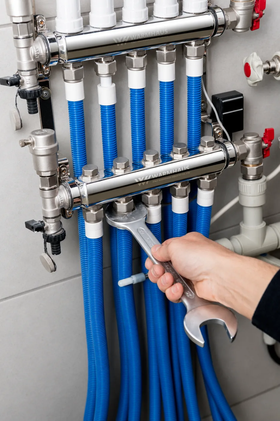
Balancing needs less equipment than most commissioning tasks, which is why it is so often skipped and so often the root cause later. You need the manifold’s flow meters, the designer’s flow schedule, two contact thermometers for ΔT across supply and return, a pressure gauge on the fill point, and the hand tools for the meter and return-valve caps.
The record matters as much as the setting. A commissioning sheet listing room name, loop length, calculated flow, measured flow and final meter position turns balancing into a document — often a handover requirement on tendered projects. Request the manifold and controls technical specifications if you need flow-meter ranges and connection dimensions.
VII. Manifolds Built to Be Balanced
Balancing is only as good as the hardware you are balancing. A flow meter with a drifting scale gives a number you cannot trust; a manifold bar with inconsistent port machining gives different loops different starting resistances before a pipe is connected. WARMHAUS is a manufacturer of PPR, PEX and brass piping systems — not a trading company. The machining lines producing the brass underfloor heating manifolds are our own, so port geometry and flow-meter seats are held to one internal standard. Brass stock is 57-3 and CW617; the PEX and PERT loops are our own extrusion, and the actuators and thermostats share the catalogue.
For a distributor that means one account instead of four for a complete radiant floor package. Manufacturing since 1993, ISO 9001 / ISO 14001 / ISO 45001 certified, EU CE marked and SGS tested, no MOQ, standard lead time 45 days. Tell us the port counts, loop diameters and market you supply, and we will send manifold specifications, the controls range and distributor terms. Certificates: available on request.