A thermostat that will not drive your actuators is worthless no matter how good the display is. Almost every underfloor heating control problem that reaches a distributor’s counter is a specification mismatch, not a fault: a 230 V thermostat wired to 24 V heads, a volt-free contact expected to power an actuator it cannot power, a floor sensor ordered without the probe, or a unit that will not sit in the back-boxes that market uses. Choosing an underfloor heating thermostat means working through five specifications in order — switching voltage, output type, sensor configuration, mounting format and actuator load — and only then asking whether it is dial, digital, programmable or wireless.
The technical values below are general industry guidance, not a WARMHAUS specification — actuator current draw, sensor resistance curves and switching capacity vary by model, so always confirm against the datasheet of the thermostat and actuator you are actually buying before you commit a control schedule to a tender.
I. What the Thermostat Has to Do Before It Is Allowed to Be Clever
In a hydronic system, the thermostat has one job that cannot be compromised: sense a temperature and switch a load. It reads the room, the floor, or both, compares it to a setpoint, and closes a circuit that energises the electrothermal actuators on the manifold outlets for that zone. Everything else the unit does — scheduling, adaptive start, app control — sits on top of that switching function and is irrelevant if the switching function does not match the hardware.
So the thermostat cannot be selected on its own. It is one third of a chain — thermostat, wiring centre, actuator — and the chain has to agree on voltage and on how much current the contact can carry. Settle the zoning first, because the number of zones sets the number of thermostats and the actuators each one drives. The mechanical side of that chain is covered in our underfloor heating manifold range; this article is about what sits above it.
A thermostat is not selected by its interface. It is selected by the load it has to switch and the sensor it has to read.
II. Decision One — Switching Voltage: 24 V or 230 V
This is the first fork and the one that renders every other decision moot if you get it wrong. Electrothermal actuators are commonly supplied in 24 V and 230 V versions, and the thermostat has to switch the same voltage its actuators run on. A 230 V thermostat cannot drive 24 V heads without a transformer and a wiring centre designed for it; a 24 V thermostat switching directly onto a 230 V head is simply the wrong product.
In practice the choice is made by the wiring centre and the market, not by preference. A 24 V control layer uses a transformer inside the wiring centre and is often preferred for larger multi-zone residential and light commercial systems, where extra-low-voltage control wiring is easier to route and terminate. A 230 V layer keeps the topology simpler — mains straight from the wiring centre to the head — and is common in smaller installations and in markets where that is what the trade stocks. Neither is technically superior for a domestic floor; what matters is that the whole zone runs on one voltage end to end. For a distributor that is a stocking decision: splitting a small stock across both voltages in every model line fragments inventory, so most importers set one voltage as the house standard and bring in the second only for project orders.
III. Decision Two — Output Type: Switched Live or Volt-Free
The second specification is what the output terminal actually delivers, and it is the one most often misread from a catalogue photo. A switched-live output passes the supply through the thermostat and out to the load: feed it 230 V and it sends 230 V to the actuators when it calls for heat. That is the arrangement for driving heads directly.
A volt-free (dry) contact carries no supply of its own. It is a switch that closes, and something else — a wiring centre, a boiler input, a zone valve controller — provides the power. Volt-free is what you need when the thermostat has to talk to a heat source or a controller rather than power a head. What it cannot do is energise an actuator by itself.
The failure mode is quiet and expensive: the thermostat is wired, the display works, the setpoint is set, and nothing on the manifold opens, because a dry contact was wired where a switched live was needed. Establish this from the datasheet before the order, not on the second site visit.
IV. The Underfloor Heating Thermostat Selection Table
The table below sets out the specifications that decide compatibility, what each one governs, and the failure that follows when it is mismatched. Use it as the checklist you run against any thermostat datasheet before it goes onto a stock list or into a tender submission.
| Specification | Typical options | What it decides | What a mismatch causes |
|---|---|---|---|
| Switching voltage | 24 V · 230 V | Which actuator heads the unit can drive | Heads never open, or are damaged by overvoltage |
| Output type | Switched live · volt-free (dry) contact | Whether the thermostat powers the load itself | Correctly wired thermostat that opens nothing |
| Switching capacity | Stated in A or VA; compare against actuator starting current, not holding | How many actuators one channel may carry | Overloaded contact, intermittent or welded operation |
| Sensor configuration | Air · floor probe · air + floor limit | What is actually regulated and protected | Floor overheating, or a floor limit that cannot be set |
| Floor probe length | Commonly supplied around 3 m | Whether the probe reaches the screed from the box | Probe too short; joint buried in the wall |
| Mounting format | Panel sized to common wall back-boxes | Whether it fits the boxes used in that market | Custom cut-outs, proud plates, rejected finish |
| Control action | Dial · digital · programmable | Setpoint precision and scheduling capability | Setback impossible; occupants override manually |
| Connectivity | Wired · wireless · WiFi | Commissioning route and retrofit feasibility | Wiring routes specified that the building cannot take |
| Ingress protection | Stated IP rating on the datasheet | Suitability for bathrooms and wet rooms | Unit specified into a location it is not rated for |
| Supply arrangement | Mains-powered · battery (wireless units) | Whether a permanent supply is required at the box | Dead thermostat, or a supply run that was never priced |
Values and options are general industry guidance, not a WARMHAUS-specific specification. Switching capacity, sensor resistance curves, probe lengths and IP ratings differ between models and manufacturers. Always confirm against the datasheet of the thermostat and the actuator you are using before finalising a control schedule.
Two rows carry more weight than the rest. Switching capacity is the one installers discover late, and it is routinely calculated from the wrong number. An electrothermal actuator does not switch mechanically; it warms a wax element, and the current it draws during that warm-up phase is substantially higher than the current it settles to once the head is open and merely holding position. Datasheets normally quote both, as a starting or inrush figure and an operating or holding figure. The holding figure is the one people multiply, because it is the one printed largest — and it is the wrong one, because every head on a channel is energised at the same instant when the thermostat calls, so their starting currents coincide.
That coincidence is what welds contacts. A relay contact sized on holding current sees several times that at every call for heat; it survives this for a while, then the contact surfaces pit and eventually stick closed, at which point the zone heats permanently and reads as a stuck actuator. So multiply the starting figure, not the holding figure, by the number of heads on the channel, and compare that against the thermostat’s stated switching capacity. Where a zone has more loops than the contact can take, drive the actuators from a wiring centre channel or a relay module instead of directly from the thermostat. Both figures vary by model and voltage class — take them from the actuator datasheet rather than assuming a typical value. Sensor configuration is the one specifiers discover late, and it is worth its own section.
V. Decision Three — Air Sensor, Floor Sensor, or Both
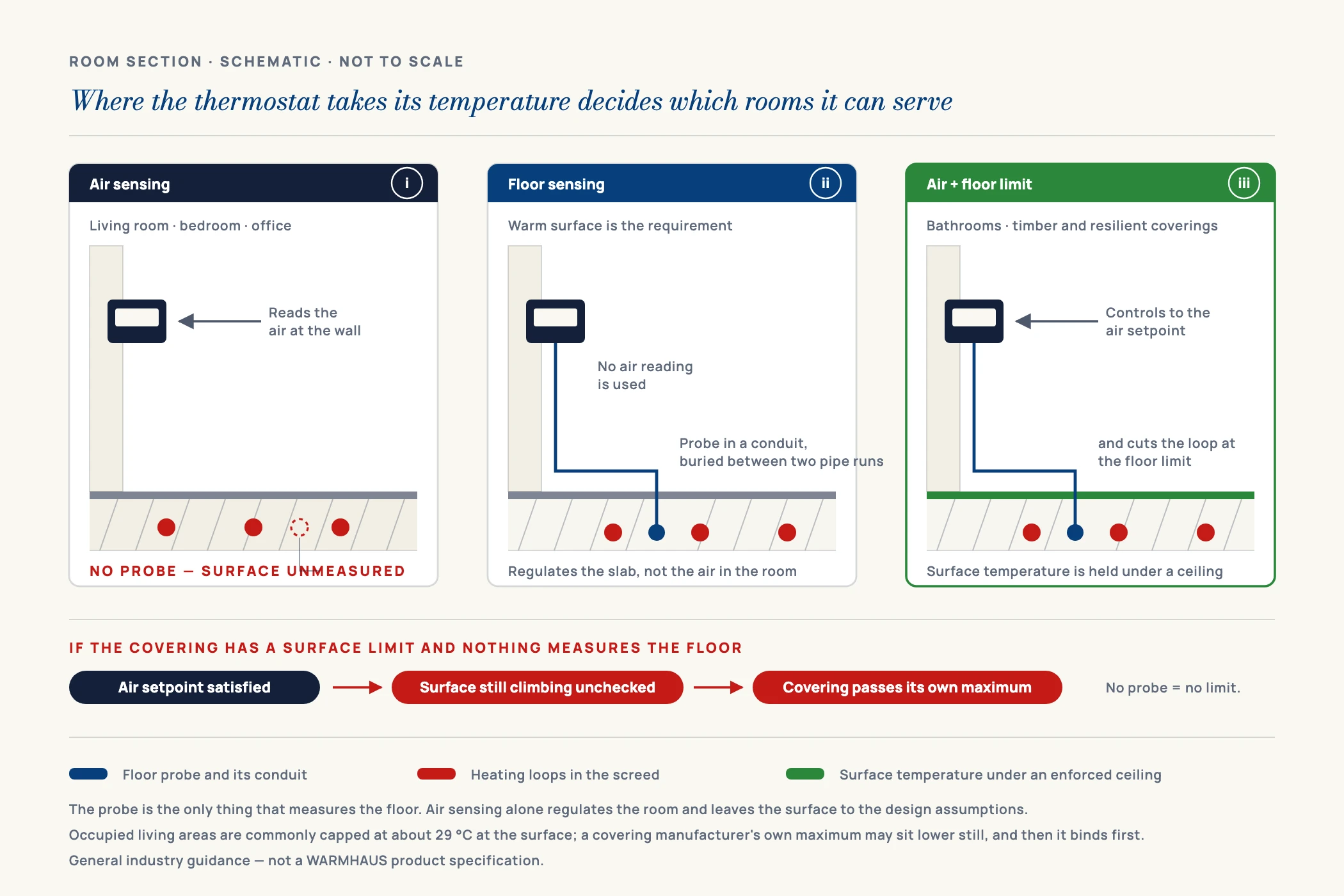
A thermostat can regulate on the air temperature it reads at the wall, on a floor temperature read by a probe in the screed, or on both — air control with the floor probe acting as a limit. The third arrangement matters most for underfloor heating, and it is regularly left off the order.
Air only is the default and is adequate for a normal habitable room with a conventional floor finish. Floor only regulates the slab rather than the air, and is used where the requirement is a warm surface rather than a controlled air temperature — a bathroom floor being the standard case.
Air plus floor limit is the arrangement to specify wherever the floor covering imposes a maximum surface temperature. The floor probe is what enforces it: the thermostat controls to the air setpoint but cuts the loop if the floor reaches the limit. Without that probe there is nothing between an aggressive flow temperature and a damaged floor except the design assumptions.
Two separate limits apply, and they are often confused. The first is the comfort and design limit on the floor surface, which comes from the EN 1264 / ISO 11855 standard family for embedded surface heating. As commonly applied, occupied living areas are capped around 29 °C, bathrooms and wet areas around 33 °C, and perimeter or edge strips near glazing around 35 °C. These are general design figures whose exact values and national application vary by edition and market. The second is the covering manufacturer’s own limit, which is a material constraint rather than a comfort one: timber, engineered board, vinyl and many resilient finishes carry a stated maximum, and for temperature-sensitive coverings this is frequently around 27 °C — below the general comfort cap, which is precisely why it binds first and why it is missed.
Set the floor limit to whichever of the two is lower, and take the covering figure from that specific product’s own documentation rather than a typical value, since it is the one that varies most and the one that voids a warranty. Where the covering is chosen after the floor is laid, set the limit for the most sensitive finish the client might realistically select. These are general industry guidance figures for planning; the binding numbers on any job are the applicable national standard and the flooring manufacturer’s published limit.
Three practical points follow. Order the probe with the thermostat — where the floor sensor is a separate part number, it is the part that gets forgotten. Install it in a conduit within the screed, between two pipe runs rather than on top of one, so it can be withdrawn and replaced without breaking out the floor. And check the supplied probe length against the real distance from back-box to sensing point; a probe short by half a metre becomes a buried joint. Loop layout determines where the probe can sit, which is why sensor decisions belong with the rest of the underfloor heating system design rather than at the end of it.
VI. Decision Four — Mounting Format and the Back-Box Problem
The specification that never appears in a marketing comparison and always appears in a site complaint is the mounting format. A thermostat has to land on the wall boxes that market actually uses. If the panel does not correspond to a common back-box size, someone is enlarging an opening in a finished wall, or the plate sits proud of the plaster and the main contractor rejects the finish.
The practical difficulty is that back-box formats are regional, not universal. Different markets have standardised on different square and round wall-box patterns, and a thermostat face designed around one of them will not sit correctly on another. So this is a question to settle by market before anything else in the range is discussed: establish which box pattern the local trade builds into its walls, then check the thermostat’s stated panel dimensions and fixing-centre spacing against it. Panel size and fixing centres are stated on the thermostat datasheet — confirm them against the boxes your market uses rather than assuming a common standard, and request the dimensioned drawing where the datasheet is not explicit. Model and specification details for our range are set out on the underfloor heating controls page. A thermostat that does not fit the boxes your market builds into its walls will not be specified twice.
Depth matters as well as the face. A wireless unit with a battery compartment, or a thermostat with a large terminal block, needs room behind it, and shallow back-boxes in blockwork get tight once the conductors are folded in.
VII. Decision Five — Wired, Wireless, or App-Connected
Only once the four decisions above are settled does the interface question become useful. Treat it as a question about the building and the buyer, not about features.
Wired is the default for new build
Where the wall is open and cable can run from the thermostat back to the wiring centre, wired is simplest and there is no battery to replace. Specify the cable route at first fix, before the plaster.
Wireless is for retrofit and finished walls
Where control wiring was never installed, a wireless thermostat and a receiver at the manifold avoids chasing walls. In return you take on batteries, pairing and signal path — check the stated range against the wall construction, and note that a manifold in a metal cabinet is a poor position for a receiver.
Programmable earns its cost through setback
A floor has thermal mass and responds slowly, so scheduling is about setback periods rather than sharp on-off cycling. Specify programmable where the occupancy pattern is predictable; where it is not, a simple digital unit at a stable setpoint often performs better.
WiFi is a sales feature with a support cost
App control sells well and adds a support channel you did not previously have — network setup, account recovery, firmware. Stock it selectively rather than making it the range default.
Confirm the actuator action before commissioning
Electrothermal heads are supplied normally closed or normally open, and the two behave in opposite ways when the thermostat is not calling for heat. Confirm which type is on the manifold before anyone concludes the thermostat is faulty.
VIII. Building the Stock List: How Many Variants Do You Actually Need
Distributors overstock the control layer more than any other part of an underfloor heating system, because the thermostat is where variants multiply. Every combination of voltage, sensor configuration, control action and connectivity is a separate part number, and the matrix grows faster than the demand.
The stock lists that work are narrow and deliberate. Pick one switching voltage as the house standard and hold the second only against confirmed project orders. Carry two control actions, not four — a simple digital unit as the volume line and one programmable unit above it. Hold the floor probe as a stocked line in its own right, because it is the item most often omitted from an order and most often needed the same week. Then stock the layer as a set: a thermostat on its own is slow-moving, while a thermostat with the actuators it drives and the manifold those actuators thread onto is a system your customer buys in one order — and the compatibility question is answered before the goods ship.
IX. Ordering the Control Layer From One Source
Every mismatch in this guide has the same origin: the thermostat, the actuator and the manifold were specified separately, from different suppliers, and the datasheets were never laid side by side. WARMHAUS manufactures the brass manifold and supplies the control layer that mounts to it. We are a manufacturer of PPR, PEX and brass piping systems, not a trading company: the extrusion, injection-moulding and machining lines are our own, so the manifold outlet and the actuator seat machined into it are held to one internal standard. The thermostats and electrothermal actuators are supplied against that manifold as a set, which means the switching voltage, the output type and the actuator thread are reconciled before the goods ship instead of on a second site visit.
For importers that also changes what an order looks like. Manufacturing since 1993, ISO 9001 / ISO 14001 / ISO 45001 certified, EU CE marked and SGS tested, with no MOQ and a standard lead time of 45 days, a first order can be a mixed one — thermostats, actuators, valve and flow-meter sets, manifolds and pipe in a single consignment — instead of a minimum quantity you must justify before the range is proven in your market. Certificate documents and full model specifications are available on request.
Tell us your market, your standard switching voltage and the back-box format your trade builds into its walls. Request the underfloor heating controls specification sheet and we will confirm what fits your system before you place an order.