Almost every underfloor heating system that heats the wrong rooms was wired correctly at every individual terminal. That is the difficulty with a wiring centre: nothing is loose, no conductor is in the wrong hole, and the system still misbehaves — the fault is in the logic, not the connection. A wiring centre is a small distribution box beside the manifold that collects a call for heat from each room thermostat, powers the actuator heads on the loops serving that room, and tells the circulating pump and heat source that water is now wanted. This guide covers what lands on each terminal, how many heads a channel will carry, and the sequence that separates a commissioned system from one that merely has power.
Arrangements described below are general industry guidance on how underfloor heating control wiring is commonly organised across the trade. They are not a WARMHAUS specification, nor a substitute for local electrical regulations. Confirm every value against the datasheet of the wiring centre, thermostat and actuator you are using, and have the final connection made by a qualified electrician working to the wiring rules in force where the system is installed.
I. What a Wiring Centre Is, and Why the Manifold Has One
A manifold with no controls is a plumbing component: water in, water out, a valve on each loop that somebody sets by hand. The moment rooms are to hold individual temperatures, every loop needs an actuator head, and every head needs a switched supply that arrives only when its room asks for heat. Running each thermostat directly to each head would mean pulling cable from every room to every outlet. The wiring centre exists so you do not have to.
Physically it is a plastic enclosure mounted inside or beside the manifold cabinet, with a row of numbered channels along the front. Each channel is a small group of terminals: one set for the thermostat that owns it, one set for the actuators it drives. Behind them sit the shared terminals.
The wiring centre is the only place in an underfloor heating system where the plumbing and the electrics have to agree with each other. Everything that goes wrong at commissioning goes wrong here.
Understanding the hydraulic side first makes the wiring obvious rather than arbitrary. If the relationship between loops, outlets and flow rates is not yet clear, our guide to the brass underfloor heating manifold explains the layer the control wiring sits on. Wire in ignorance of the loop layout and you will group the wrong outlets onto one channel.
II. The Five Things That Terminate in the Box
Whatever the make, five families of conductor arrive at a wiring centre, and confusion between them causes most of the trouble.
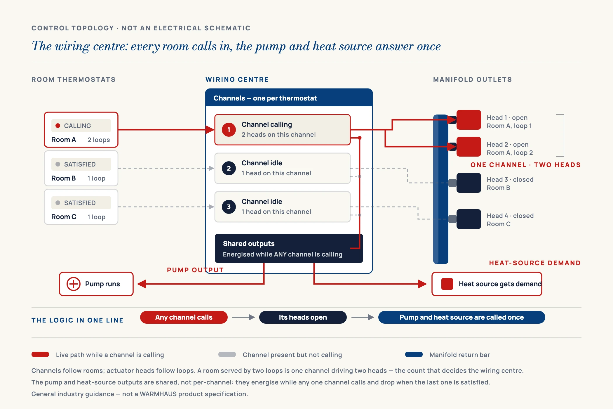
The incoming supply powers the unit itself — on a low-voltage system feeding a transformer, on a mains system feeding the channels directly. Thermostat cables run from each room back to its channel: a simple switching thermostat needs only a switched pair, while a powered thermostat with a display or clock needs a permanent supply as well, which is why so many installers arrive with two-core cable and need four or five. Actuator tails run from the manifold outlets into the channel that drives them — one tail per head, and heads sharing a room share a channel. The pump output is a switched live that energises the circulating pump when any channel calls. The heat-source output tells the boiler, heat pump or heat interface unit that there is now a load, most often through a volt-free contact, because the heat source wants a clean pair of contacts and not somebody else’s voltage.
Mistakes cluster on two of these five. Thermostat cabling is decided at first fix, when the cable is already buried — so specifying the thermostat late means running the wrong cable early. And the heat-source connection is usually improvised on the day, because the underfloor heating package and the boiler come from different suppliers with different terminal conventions.
III. The Terminal Schedule
The table below is the schedule to work through before an electrician arrives, not after. Each row is a connection group that has to be agreed between the wiring centre, the thermostat, the actuator and the heat source. The right-hand column is what happens when that agreement is missing — usually not a dead system but one that works strangely, which is far harder to trace.
| Connection group | Typical arrangement in the trade | Decided by | Symptom if it is wrong |
|---|---|---|---|
| Incoming supply | Fused supply to the unit; low-voltage units feed an internal transformer | Wiring centre specification | Nothing operates, or transformer runs hot under load |
| Thermostat, switching type | Switched pair from the stat to its channel | Thermostat model | Zone stays dead if the stat needed a permanent live |
| Thermostat, powered type | Permanent supply plus switched return, more cores | Thermostat model | Display blank; cable already buried at first fix |
| Actuator tails | One tail per head into the channel serving that room | Loop layout, not room count | One loop of a two-loop room never opens |
| Channel load | Head starting figure × heads on the channel, versus channel rating | Wiring centre rating | Channel overloads where rooms have several loops |
| Control voltage | One voltage class throughout: stats, heads and centre | Whole control architecture | Heads never open, or fail immediately on power-up |
| Pump output | Switched output energised when any channel calls | Wiring centre logic | Pump runs against closed loops, or never runs |
| Heat-source output | Commonly a volt-free contact to boiler or heat pump | Heat-source terminal convention | Heat source ignores the call, or is back-fed voltage |
| Pump overrun | Timed run-on after the last channel drops | Wiring centre feature set | Residual heat trapped in the mixing group |
| Actuator first-open | Some heads ship unpowered in a partly open state | Actuator model | Flushing appears fine, then loops shut after power-up |
| Earthing and segregation | Extra-low-voltage and mains conductors kept apart | Local wiring regulations | Regulatory non-compliance; nuisance interference |
Values are general industry guidance, not a WARMHAUS-specific specification. Terminal naming, channel ratings, voltage class and available features differ by model and are confirmed per model on the datasheet — always follow the datasheet supplied with the wiring centre, thermostat and actuator you are using, and the electrical regulations applying at the installation site.
Running that schedule against a real project — outlet count, loops per room, thermostat type per room — is a thirty-minute exercise that removes almost every callback described below. To have it checked, request the control-layer wiring schedule for your manifold configuration and tell us the outlet count, the number of rooms and the control voltage you are working to.
IV. Channels, Loops and Rooms — the Counting Problem
The single most common ordering error in underfloor heating control is counting rooms when you should be counting loops. A channel corresponds to a thermostat — that is, to a room. But actuators correspond to loops, and a large open-plan area may be served by three or four loops from the same manifold. Those heads all belong to one channel, but they are three or four heads, three or four sets of tails, and three or four times the load on it.
So there are two counting exercises, which people habitually merge into one. The channel count comes from the room schedule; the actuator count comes from the manifold outlet schedule, and is almost always the higher of the two. Order to the room count and a share of the loops arrive without heads — an awkward shortfall to discover at second fix against a 45-day standard lead time.
The load calculation follows from the same distinction. Each channel carries a maximum load; each head draws a small but non-zero wattage. The number that catches people is not the running figure. An electrothermal head warms a wax element to open, and the current it draws while that element is heating is appreciably higher than the current it settles to once the head is open and simply holding position. Datasheets normally quote both — an operating or holding figure and a higher starting, inrush or peak figure. As general industry guidance, a mains-voltage electrothermal head is commonly in the order of a couple of watts holding, with the starting draw a multiple of that for the first minutes; low-voltage heads differ again. Size the channel on the starting figure, not the holding figure, because every head on a channel is energised at the same instant when the thermostat calls.
So the check is: take the starting figure from the actuator datasheet, multiply by the number of heads on the busiest channel, and compare that against the channel rating on the wiring centre datasheet. In a house of single-loop bedrooms this never binds; in a project with a large living space and a kitchen-diner, it can bind on several channels at once. The remedy is a relay module or splitting the room across two channels tied to the same thermostat — decided at design, not at commissioning. These are general figures for planning only; the binding numbers are the ones printed on the datasheets of the actuator and wiring centre you are actually installing. The manifold installation sequence sets out where in the build this schedule should be finalised, which is earlier than most programmes assume.
V. Voltage Class — One Decision for the Whole System
Control components are commonly offered in a low-voltage class around 24 V and a mains class around 230 V. This is not a component-level choice made three times over; it is one architectural decision binding the wiring centre, every thermostat and every actuator head together. Low voltage puts a transformer in the centre and keeps mains potential out of the cabinet; mains switches heads directly, a shorter bill of materials with live conductors terminating at the manifold. Neither is superior, and the market splits by region and installer habit rather than engineering merit.
What matters is that the class is uniform. A 230 V head on a 24 V channel simply never opens, and the zone reads as a plumbing fault until someone checks the head marking. A 24 V head on a mains channel is destroyed on power-up and can take the channel with it. Because the two versions are visually near-identical, this is caught on the order line or not at all — so for distributors the consequence is inventory discipline: stock the class your market’s electricians actually wire rather than splitting stock. The full thermostat and actuator range is specified per model on its datasheet, available on request.
VI. The Wiring Faults That Generate Callbacks
These failures recur, roughly in the order a commissioning visit meets them. Each is cheap to prevent, expensive to find.
Thermostat cable specified after it was installed
Powered thermostats with displays or timers need more cores than a simple switching stat, and the cable is buried at first fix, months before the thermostat is chosen. Decide the model before the walls close, or run the higher core count as insurance — retro-fitting cable through a finished wall costs more than every thermostat in the house.
Heads wired to the wrong channel
Loops leave the manifold in an order that has nothing to do with the room numbering on the wiring centre. Label each loop at the outlet during pipe installation, then label the tail at the head. Without labels, working out which outlet feeds which room after the screed has gone down means heating one loop at a time and walking the floor.
Heat-source contact back-fed with voltage
Most boilers and heat pumps expect a volt-free pair of contacts on their room-stat terminals. Sending a switched live into terminals designed for a dry contact is a genuine fault. Confirm which the heat source wants before the connection is made, and use the wiring centre’s volt-free output if it has one.
Commissioning judged in thirty seconds
Electrothermal heads take several minutes to open, because they warm a wax element rather than switching. Energise a channel, then wait. Perfectly good actuators are pulled off manifolds because nothing happened immediately.
Pump wired to a permanent supply instead of the switched output
The circulator is connected to a convenient live rather than the wiring centre’s pump terminal, so it runs continuously against closed actuator heads. The system heats acceptably, which is why it survives handover, but the pump is dead-heading whenever no channel calls. Take the pump supply from the switched pump output, and keep the wiring centre’s overrun timer — a deliberate run-on after the last channel drops is a different thing and is usually wanted.
Channel loaded past its rating by a multi-loop room
One thermostat on a large open-plan area can drive three or four heads from a single channel. Each head draws more current while its element is warming than it does once open and holding, so the figure that matters for the channel rating is the higher one, and several heads energising together arrive at the same moment. Compare that combined figure against the channel rating on the datasheet and use a relay module or a second channel where it does not fit.
VII. The Commissioning Sequence
Order matters more than technique here. Pressure-test the loops and leave them under test pressure through the screed pour, before any head goes near an outlet. Fit the actuator heads only after the screed is down and the wet trades are finished — a small plastic head left exposed for six weeks is a cracked head. Balance the loops on the flow meters against the design rates. Only then energise the wiring centre.
With power on, work one channel at a time. Call for heat on a single thermostat, wait several minutes, and confirm the correct heads have lifted, the pump has started and the heat source has received the call. Then drop that channel, wait for the heads to close, and move to the next. Testing one channel at a time is the only way to catch a crossed pair of tails; testing them all at once tells you the system has power and nothing else. Record which outlet serves which room and which channel drives which outlets, and note it inside the cabinet door — the next person to touch the system will need that schedule, and it is almost never written down.
VIII. Sourcing the Control Layer as One Matched Package
Everything above is a compatibility argument. The thermostat has to match the wiring centre on voltage class and switching type; the actuator has to match the centre on voltage and load, and the manifold on thread. When those parts come from four suppliers, every mismatch surfaces at commissioning — and the person holding the invoice is the one who bought them.
WARMHAUS manufactures the brass manifold the control layer sits on, and supplies the controls that go with it. We are a manufacturer of PPR, PEX and brass piping systems, not a trading company — the extrusion, injection-moulding and machining lines are our own, which is why the manifold outlet and the actuator seat machined into it are held to one internal standard. The control components that mount to it — thermostats, electrothermal actuators and the wiring centre — are supplied alongside the manifold as one package, so the voltage class, switching type and actuator thread are checked against each other before the order ships rather than at commissioning. That is the compatibility question answered by the supplier instead of by the installer. Voltage class, switching type and thread are confirmed per model on the datasheet: available on request. Manufacturing since 1993, ISO 9001 / ISO 14001 / ISO 45001 certified, EU CE marked and SGS tested, with no minimum order quantity, so a first control package can be trialled before it is committed to volume. Standard lead time is 45 days from order confirmation. The thermostat and actuator range, the brass manifolds they mount to and the installation tools and pipe-fixing accessories consolidate into one consignment.