The actuator is the smallest part of an underfloor heating system and the one most likely to be ordered wrong. It is a thumb-sized head that screws onto a manifold outlet and opens or closes that single loop when the room thermostat calls for heat. Nothing about it looks difficult — which is exactly why a container arrives with 240 heads that will not thread onto the manifolds sitting beside them, or that are wired 230 V into a 24 V wiring centre. Selecting an underfloor heating manifold actuator comes down to four specifications that must all agree with parts made by someone else: voltage, normally-closed or normally-open action, the valve thread on the manifold outlet, and the wiring-centre logic behind it. This guide takes them one at a time.
Figures given below are general industry guidance, describing how electrothermal actuators are commonly specified across the trade. They are not a WARMHAUS specification. Confirm every value against the technical datasheet of the actuator, valve and manifold you are actually using before you order or wire anything.
I. What the Actuator Actually Does
An electrothermal actuator contains no motor. Inside is a wax or expansion element wrapped in a small heating resistor. Apply voltage and the resistor warms the element; the element expands and drives a plunger against the valve stem on the manifold outlet. Cut the voltage and the element cools, contracts, and a return spring pushes the plunger back. That is the whole mechanism — a heater, a wax capsule and a spring. It is why these heads are quiet, why they have no motor, gearbox or bearing to wear out, and why they are slow.
“No moving parts to wear” is not the same as “lasts forever”, and it is worth separating the two now because the distinction decides how you order spares. What ages an electrothermal head is not mechanical wear but the things that have no service life stated on a bill of materials: the heating element sits under power for as long as the zone is calling, the wax capsule is thermally cycled every time the room satisfies, the return spring is cycled with it, and the plastic housing lives in a cabinet that gets hot. Add the failures that have nothing to do with the mechanism at all — a cap cracked by another trade, a cable pulled at the wiring centre, a head fitted to the wrong voltage — and a head is a component that gets replaced occasionally over the life of a system, while the brass manifold underneath it does not. Neither statement contradicts the other: nothing rubs, but something is being heated and cycled.
An electrothermal actuator does not switch. It warms up, expands, and takes several minutes to change its mind — and that lag is a design feature, not a fault.
Slow is intentional. Typical opening and closing times quoted across the industry sit in the region of two to five minutes, and that lag matches the thermal inertia of a heated screed, which responds over hours rather than seconds. The consequence for the specifier is that an actuator is not a diagnostic you can watch: after wiring, you wait several minutes before concluding the head is dead. More than one perfectly good actuator has been pulled off a manifold because nothing happened in the first thirty seconds. If the way the actuator sits within the wider loop and mixing arrangement is not yet clear, our explanation of how an underfloor heating system is put together sets the context this guide assumes.
II. Decision One — Voltage: 24 V or 230 V
Electrothermal actuators are commonly supplied in a low-voltage version around 24 V and a mains version around 230 V. Neither is technically better; they belong to different control architectures, and the choice is made by the wiring centre and thermostats, not by the actuator.
Low-voltage systems dominate where the control layer is centralised: a wiring centre with a transformer feeds thermostats and actuator heads on the same low-voltage bus, which lets thin control cable run to each room. Mains-voltage systems remain common where a thermostat switches the head directly and no transformer is wanted in the cabinet — a simpler bill of materials, but every conductor into the manifold cabinet is now live at mains potential.
Two practical rules follow. First, never mix voltages on one manifold — but the two directions of that mistake do not behave the same way, and the difference matters on site. A 230 V head fed 24 V simply never opens: the element cannot reach expansion temperature, so the loop stays shut, the room stays cold, and the fault is obvious and harmless. The reverse is the dangerous one. A 24 V head fed from mains is not a switch that trips instantly. The heating element is a resistor, so mains on a low-voltage element is a gross overpower condition that plays out thermally: the element heats far beyond its design point over a period of seconds to tens of seconds, the head may well drive fully open on the way, and it then fails — sometimes open-circuit and quietly, sometimes with a scorched cap, melted housing or a short that takes the wiring centre channel with it.
That lag is precisely why this mistake is so expensive. Because the first symptom can be a head that appears to work, a miswired manifold can pass a hurried commissioning check and fail days later, and heads that survived the first energisation can be degraded and fail one by one over a season. Do not rely on seeing the fault; rely on never creating it. Verify the voltage marking on the head against the wiring centre output before anything is energised, and keep one voltage on any given site. Second, buyers stocking for a market should pick the voltage that market’s electricians actually wire and keep it consistent, rather than splitting inventory. For distributors, this is the single most common source of returns on control parts, and it is entirely avoidable at the order stage.
III. The Selection Table
The table below is the checklist to run before an order is placed. Each row is a specification that has to be agreed between the actuator, the manifold and the wiring centre — the right-hand column is what goes wrong when it is not.
| Specification | Common options in the trade | Decided by | If it is wrong |
|---|---|---|---|
| Supply voltage | ~24 V low-voltage · ~230 V mains | Wiring centre & thermostat architecture | Head never opens (undervolt), or burns out thermally (overvolt) |
| Action on power | Normally closed (NC) · normally open (NO) | Control strategy & failure mode wanted | Every zone heats when it should be off |
| Valve connection | Threaded head-to-valve connection, size per model | Manifold outlet valve body | Head will not seat; adaptors or a rebuy |
| Stroke | Commonly ~4 mm of linear travel | Valve insert stem lift on the manifold | Stroke shorter than the stem needs; valve never fully closes |
| Closing force | Commonly of the order of ~100 N | Element and spring rating | Valve not seated against differential pressure; loop bleeds heat |
| Opening / closing time | Typically ~2–5 minutes | Element type, ambient temperature | Assumed faulty and replaced needlessly |
| Power consumption | Low, a few watts per head | Element rating | Wiring centre channel overloaded |
| Heads per channel | Depends on channel rating vs. head load | Wiring centre specification | Large rooms with two loops trip a channel |
| Position indicator | Visible open/closed indication on many models | Head design | No way to commission by eye |
| First-fix adaptor | Some heads ship with a fitting position for screed pour | Site sequencing | Heads fitted and damaged before plastering |
Values are general industry guidance, not a WARMHAUS-specific specification. Voltage, NC/NO action, thread and timings differ by model and are confirmed per model on the datasheet — always follow the datasheet supplied with the actuator, valve and manifold you are using.
Two of those rows deserve a note, because they are the ones that produce the fault nobody finds. Stroke is how far the plunger travels, and across the trade electrothermal heads for manifold valve inserts are commonly built around a travel of the order of 4 mm, because that is roughly the stem lift the common valve inserts use. Closing force is how hard the head can push that stem onto its seat against the differential pressure the circulator is producing, and published figures for this class of head are commonly of the order of 100 N. Both are general industry orders of magnitude rather than a universal figure, and both are stated per model on the datasheet — check them there before ordering.
The reason to check is that a shortfall in either does not announce itself. A head whose stroke is a fraction short of the stem lift, or whose force is not enough to seat the valve against a high pump head, closes almost fully. The zone reads as controlled, the actuator looks like it is working, and the loop bleeds a permanent trickle of hot water so the room never quite goes cold. That is the fault that gets blamed on the thermostat, the balancing or the screed for an entire season. It is also the reason an adaptor between a head and a valve insert from a different range is worth avoiding: the adaptor’s stack height eats directly into a stroke budget measured in millimetres.
Working through those rows before the purchase order goes out is the difference between a control package that installs in an afternoon and one that sits in a warehouse waiting for adaptors. If you would like this checked against a specific manifold configuration, request the actuator and manifold compatibility details for your project and tell us the outlet count and control voltage you are working to.
IV. Decision Two — Normally Closed or Normally Open
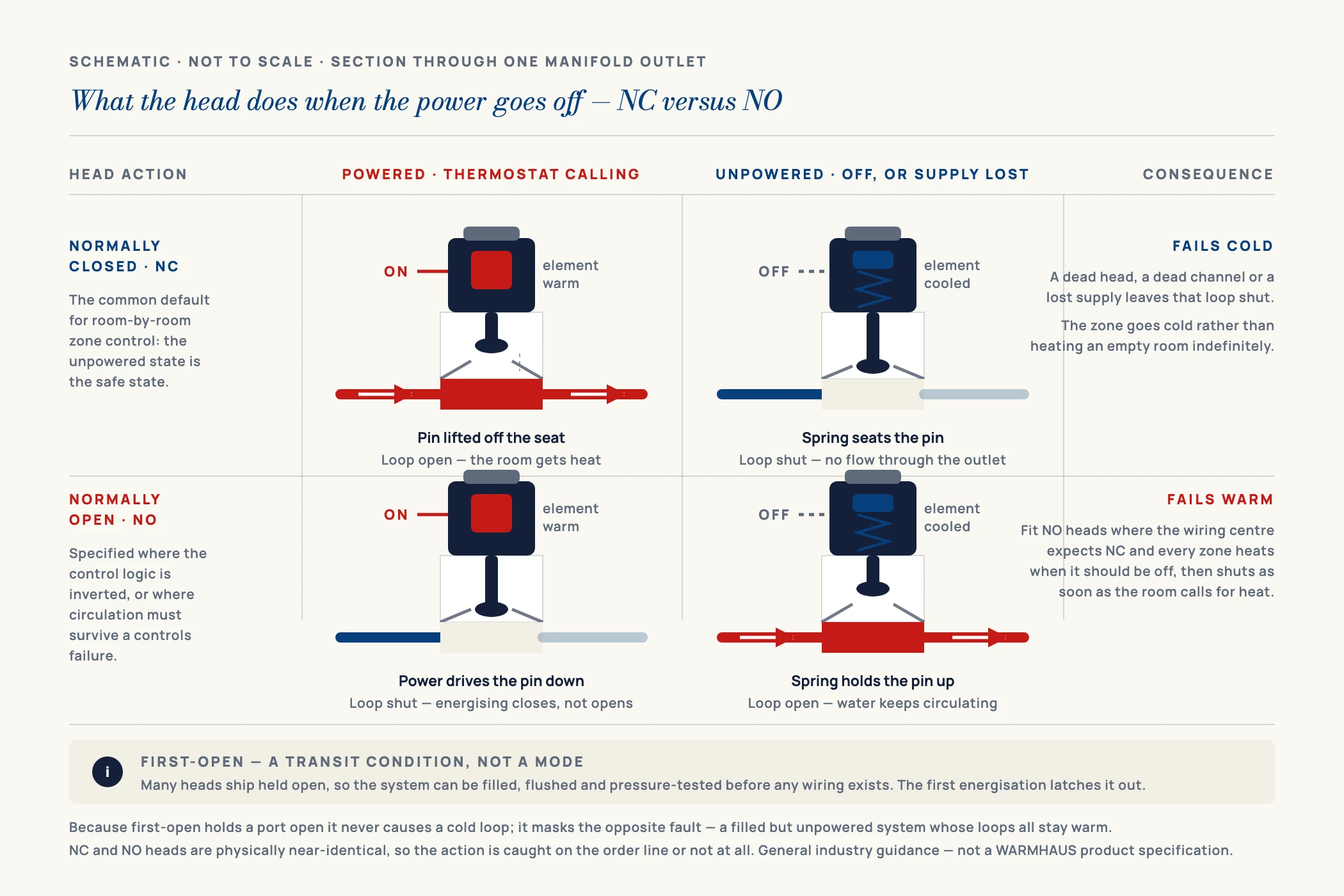
This is the specification most often left blank on an enquiry, and the one with the most visible failure. A normally closed actuator holds the loop shut when it is unpowered and opens when the thermostat energises it. A normally open actuator does the reverse: unpowered it lets water through, and applying power closes the loop.
Normally closed is the more common default in room-by-room zone control, because the unpowered state is the safe state — a failed head or a dead channel leaves that loop cold rather than heating an unoccupied room indefinitely. Normally open appears where the control logic is inverted, or where a designer wants the system to keep circulating if the control layer fails. Both are legitimate; what is not legitimate is guessing.
The failure is unmistakable on site. Fit NO heads to a system whose thermostats and wiring centre expect NC, and every zone heats whenever it is supposed to be off, then shuts as soon as the room calls. The building is warm at the wrong times and the electrician spends a day looking for a wiring fault that does not exist. Because the two versions are physically near-identical, this is caught at the order line or not at all — which is why NC or NO belongs in the enquiry alongside the voltage.
V. Decision Three — The Thread Onto the Manifold
An actuator does not mount to the manifold body. It mounts to the valve insert in the manifold outlet, and that connection is a threaded interface whose size and form is set by the manifold, not by the head. This is the mechanical half of compatibility and the one that stops an installation dead, because unlike a voltage mismatch there is no clever wiring around it.
Different manufacturers use different valve-connection standards, and heads from one range will not necessarily seat on another’s outlets. Adaptor rings exist for some combinations, but every adaptor adds stack height in a cabinet that is often already tight, and adds a tolerance chain between the plunger and the valve stem. That last point matters more than it sounds: if the adaptor lifts the head even slightly, the stroke that should fully close the valve no longer does, the loop bleeds a trickle of hot water permanently, and the room never quite goes cold. That is a far harder fault to diagnose than a head that plainly does not fit.
The clean answer is to specify the actuator and the manifold together from the start. WARMHAUS produces the electrothermal actuator, the valve and flow-meter set and the brass underfloor heating manifold on its own injection-moulding and machining lines, to one set of internal drawings, so the head lands on the outlet without an adaptor. Exact thread standard and head dimensions are stated on the product datasheet, available on request. If you are procuring a manifold and controls together, the wider manifold installation sequence shows where in the build the heads should go on — which is later than most people assume.
VI. Decision Four — Wiring Centre and Channel Loading
The fourth decision is the one that is not about the actuator at all. Heads are wired back to a wiring centre, which takes the call for heat from each thermostat, powers the corresponding actuators, and typically also signals the circulating pump and heat source. Three things about that arrangement decide how many heads you order and how they are grouped.
One head per loop, not one per room
A large room served by two or three loops needs an actuator on each of those outlets, all wired to the same thermostat channel. Counting rooms instead of loops is the classic way to under-order a control package by a fifth.
Check the channel load
Each wiring centre channel carries a maximum load. Multiply the head’s power consumption by the number of heads on that channel and compare it to the channel rating before ordering — this is where multi-loop rooms quietly exceed the limit.
Match the thermostat to the head
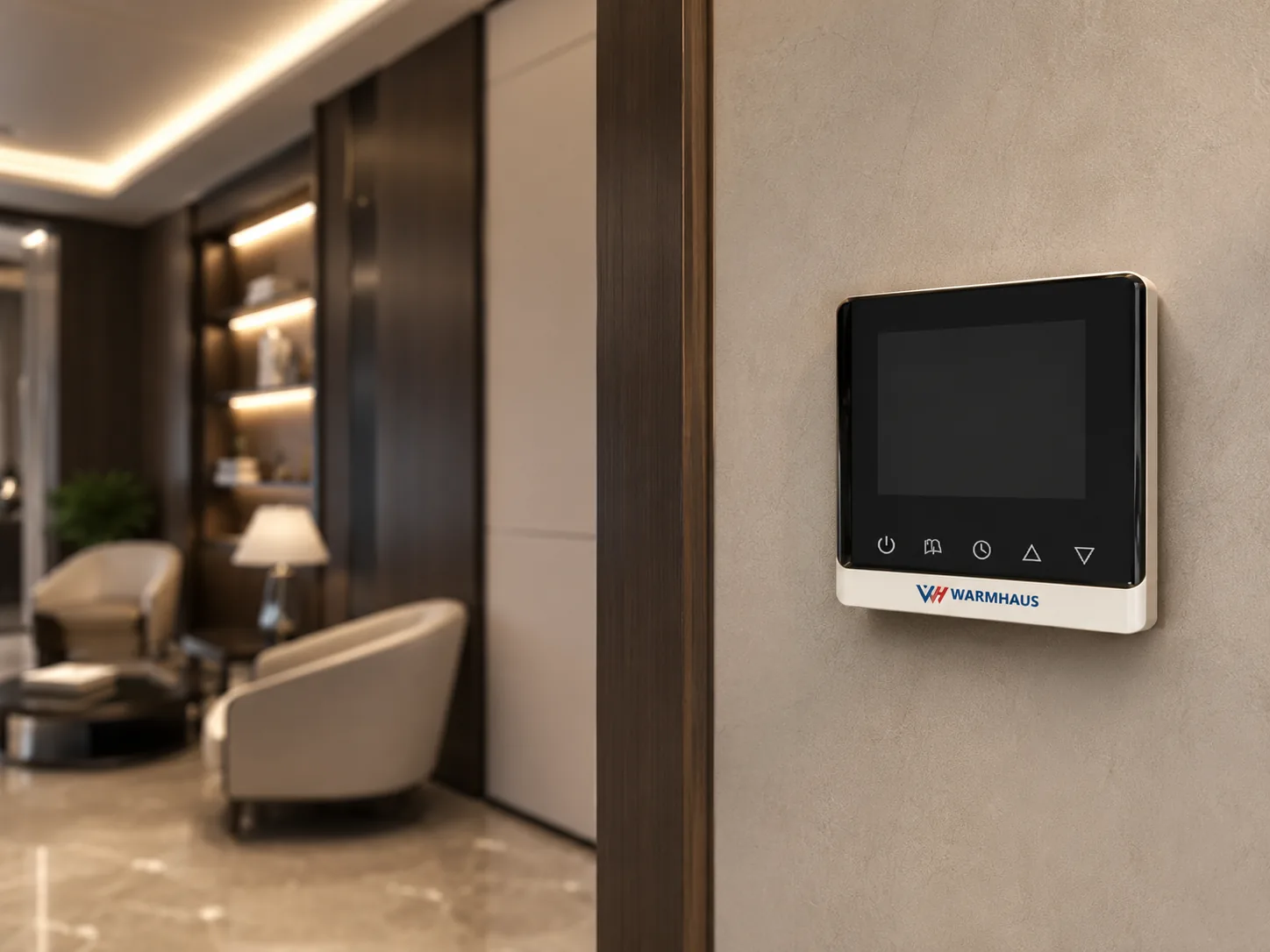
The thermostat has to switch the actuator’s voltage and speak the same NC/NO logic. WARMHAUS thermostats are engineered to drive our own actuator heads directly, so the call-for-heat signal matches without a third-party head wired in and hoped to respond the same way.
Fit the heads last
Actuators go on after the screed is poured and the pressure test is complete. Fitting them at first fix exposes small plastic heads to trades, debris and impact for weeks, and a cracked cap is not repairable on site.
Balance first, then automate
Set the loop flow rates on the flow meters before commissioning the control layer. An actuator is an on/off device — it cannot correct an unbalanced loop, and asking it to hides the real problem behind cycling zones.
Order spares with the shipment
As set out in section I, the head has nothing that rubs, but it is a powered, thermally cycled and impact-prone part, so it is replaced occasionally where the brass beneath it is not — and a single missing head strands a zone. Adding a small spare percentage to the original order costs far less than a separate consignment against a 45-day standard lead time.
VII. Ordering the Control Layer as One Package
Everything above reduces to a sourcing argument. The actuator has to agree with the manifold on a thread, with the thermostat on voltage and logic, and with the wiring centre on load. When those four parts come from four suppliers, every mismatch surfaces on site, at the worst possible moment, and the person holding the invoice is the one who bought them.
WARMHAUS makes the control layer and the manifold it sits on. We are a manufacturer of PPR, PEX and brass piping systems, not a trading company — the extrusion, injection-moulding and machining lines are our own, which is why the actuator seat and the valve interface are held to one internal standard across the range. Thermostats, electrothermal actuators, valve and flow-meter sets and brass manifolds ship as one matched package, so a distributor stocks one control kit that fits every manifold on the shelf. Voltage, NC/NO version and thread are confirmed per model on the datasheet: available on request. Manufacturing since 1993, ISO 9001 / ISO 14001 / ISO 45001 certified, EU CE marked and SGS tested, with no minimum order quantity, so a first control package can be trialled before it is committed to volume. Standard lead time is 45 days from order confirmation. Full thermostat and actuator range and the rest of the underfloor heating system come from the same production lines and can be consolidated into one container with PPR, PEX and brass lines.