Both systems warm a floor, and there the similarity ends. Hydronic radiant heating circulates warm water through continuous loops of plastic pipe embedded in screed, fed and balanced from a manifold. Electric underfloor heating lays a resistance cable or a pre-spaced mat under the floor finish and converts electricity directly into heat. The decision between them is almost never made on comfort — both deliver the same low-temperature, even-surface warmth. It is made on installed cost, running cost, floor build-up height and how long the building will be heated for. Get those four straight and the answer is usually obvious within one conversation.
This page is written for the people who have to defend the choice: the mechanical consultant or specifier writing the heating section of a tender, and the distributor or purchasing agent deciding which system to stock for a market. All figures below are general industry guidance for planning and comparison, not project design values and not WARMHAUS-specific specifications. Binding numbers come from the technical data sheet of the products you actually buy, from your project heat-loss calculation, and from the local energy tariffs that apply on site.
I. What Actually Separates the Two Systems
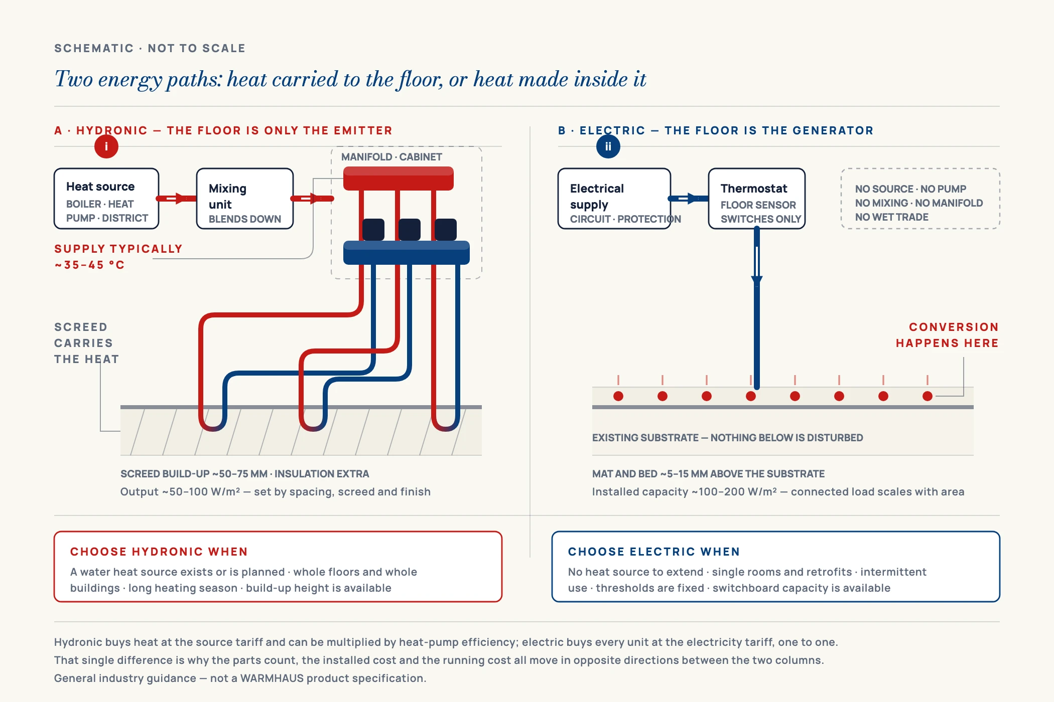
A hydronic floor is a distribution system. Heat is generated somewhere else — a boiler, a heat pump, a district connection, a solar thermal store — and the floor is simply the emitter. The loops of PEX or PE-RT barrier pipe run continuous from a manifold flow port, around the room at a designed spacing, and back to the return port with no joint inside the screed. The manifold splits the supply into zones, balances flow between loops of different lengths, and carries the actuators that open and close each circuit on a thermostat call.
An electric floor is a generation and emission system in one. There is no heat source elsewhere, no water, no pump, no manifold. A cable of a specified output per metre — or a mat with that cable already fixed at spacing to a mesh — is laid in the adhesive bed or a thin levelling layer, wired back to a thermostat, and switched. The design work reduces to matching cable output per square metre to the heat loss and getting the floor sensor in the right place.
One system moves heat that was made elsewhere. The other makes heat where it stands. Everything on the cost sheet follows from that.
That structural difference is why the two systems fail in different ways and are priced in opposite directions. Hydronic carries a large parts count — pipe, manifold, actuators, mixing unit, pump, thermostats, wiring centre — and therefore a large installed cost, but it can be fed from whatever heat source is cheapest per unit of delivered energy. Electric carries almost no parts count and installs in a fraction of the time, but every unit of heat it delivers is bought at the electricity tariff. In broad terms, hydronic pays more on day one to pay less every winter after it; electric does the opposite.
II. Hydronic vs Electric Underfloor Heating: Side-by-Side
The table below sets the two systems against each other on the criteria that actually change a specification decision. Ranges are typical industry values for general guidance only. Output figures depend on floor construction, finish resistance and design flow temperature; build-up heights depend on the screed or levelling system used; installed cost varies with market, labour rate and project size.
| Criterion | Hydronic (warm water) | Electric (cable / mat) |
|---|---|---|
| Heat source | Boiler, heat pump, district or solar thermal — floor is the emitter only | Electricity converted to heat at the cable itself |
| Typical design flow temp | ~35–45 °C supply, mixed down from the source | Not applicable — no water circuit |
| Typical output (residential) | ~50–100 W/m² depending on spacing, screed and floor finish | ~100–200 W/m² installed capacity; mats are catalogued in steps across that band, and the step chosen varies by market and by whether the floor is the primary or a supplementary heat source |
| Floor build-up added | Screed layer only: ~50–75 mm for a traditional wet screed. Insulation below the pipe is additional — the total rise above the existing slab is what a threshold has to clear, and it is commonly well above the screed figure alone. Low-profile systems reduce both. | Above the substrate: ~5–15 mm for mat plus levelling or adhesive bed, excluding any insulation board added below |
| Response time | Slow — high thermal mass, hours to reach and to fall back | Fast — low mass, warms in tens of minutes |
| Installed cost | Higher — pipe, manifold, actuators, mixing unit, pump, controls, wet trades | Lower — mat, thermostat, electrical connection |
| Running cost driver | Cost per kWh of the heat source, improved by heat-pump efficiency | Electricity tariff, one-to-one, with no efficiency multiplier |
| Best fit | Whole-house and whole-floor heating; new build; long heating seasons | Single rooms, bathrooms, retrofit over an existing floor, intermittent use |
| Zone control | Manifold actuators plus wiring centre; per-loop balancing | Thermostat per circuit; each area needs its own supply |
| Serviceability | Manifold accessible in a cabinet; buried loops are jointless by design | Cable is buried, but a damaged cable is a routine repair: the fault is located by resistance and insulation testing or thermal imaging, then the finish is opened locally and the cable jointed. Cost sits mostly in the floor finish, not the cable |
| Parts to stock | Pipe coils, manifolds, actuators, adaptors, thermostats, clips | Mats by area, thermostats, sensors, fixing accessories |
Values are general industry guidance, not a WARMHAUS-specific specification. Output, build-up and cost all shift with construction detail, floor finish, local labour rates and tariffs. Always confirm against the technical data sheet of the pipe, manifold and controls you are using, and against the project heat-loss calculation.
III. The Cost Question, Properly Framed
Most comparisons collapse when they quote a single price per square metre, because the two systems put their money in different places. A defensible comparison separates three numbers and keeps them separate.
Installed cost is where electric wins and it is not close. An electric mat is a mat, a thermostat and a floor sensor. There is no manifold cabinet to build in, no pipe to clip out, no pressure test, no screed pour to wait on, and no wet trade in the programme. A hydronic floor puts a manifold, actuators, a mixing unit, a pump, a wiring centre, hundreds of metres of loop pipe and a screed pour into the same room. For a single bathroom the hydronic parts list is absurd; for a whole villa it is proportionate, because the manifold and mixing unit cost the same whether they serve one loop or twelve.
Running cost reverses the result, and the reason is the heat source rather than the floor. Electric resistance heating converts one unit of electricity into one unit of heat — there is no multiplier available, and the price of that heat is exactly the price of electricity. A hydronic floor’s heat comes from whatever the building already has: a gas boiler priced at the gas tariff, or a heat pump that delivers several units of heat per unit of electricity because it moves heat rather than creating it. That is also why hydronic pairs so well with low-temperature sources. A floor sized to run at 35–45 °C supply lets a heat pump work near its efficient range, where a radiator circuit demanding much higher flow temperatures would not.
Lifetime cost is where the two curves cross, and where they cross depends on three local variables that no article can answer for you: the ratio of the electricity tariff to the alternative fuel, the length and severity of the heating season, and how many hours per day the space is actually heated. In a market with a short mild winter, a room heated for two hours a morning, and no existing wet heating system, the crossover may never arrive — the electric mat simply wins. In a market with a long heating season and a whole building to warm continuously, it arrives early enough that hydronic is the only serious answer.
IV. Design Constraints That Decide It Before Cost Does
In practice, a large share of projects never reach the cost comparison, because a physical constraint has already ruled one system out. These are the four that decide most often.
Floor build-up height
Measure the total rise above the existing structural floor, not the screed thickness — this is where retrofit budgets go wrong. A traditional wet screed adds ~50–75 mm of screed, but the insulation layer beneath the pipe is additional, and in a refurbishment the two together commonly put the finished floor well above what the screed figure alone suggests. An electric mat adds ~5–15 mm above its substrate, again before any insulation board. In a retrofit with door heights, staircases and thresholds already fixed, that difference is often what decides the system. Add up every layer in the build-up before pricing anything.
Whether a heat source already exists
Hydronic only makes sense where there is, or will be, a water heat source worth feeding it from. If the building has a boiler or a heat pump, adding a floor circuit is an extension of an existing plant. If it has nothing, the comparison silently includes the whole cost of a heat source, and a single-room project cannot carry that. Establish the plant before the emitter.
Heated area and continuity of use
Thermal mass is an asset in a continuously heated building and a liability in an intermittently heated room. A screed floor takes hours to come up and hours to fall back, which is ideal for steady whole-house heating and wrong for a guest bathroom used twice a day. Match the mass to the occupancy pattern, not to the room size.
Electrical supply capacity
Electric floors are sized in installed watts, so connected load scales directly with area: at a mid-band ~100–200 W/m² specification, even a modest floor becomes a load with its own circuit and protection requirements, and a large one can rival the rest of the dwelling combined. In markets where supply capacity per dwelling is constrained, the switchboard rules out electric long before the tariff does. Multiply your area by the actual mat rating and confirm available capacity before quoting.
Floor finish and its thermal resistance
Both systems have to push heat through the finish. Tile and stone pass it readily; thick engineered timber and heavy carpet resist it and force either closer pipe spacing or higher installed watts. Either way the finish is a design input, not a decoration choice made later. Fix the finish specification before final loop or mat sizing.
V. Controls: Where the Two Systems Diverge Most
Control is the part buyers underestimate. An electric floor’s control chain is short: a thermostat with a floor sensor switches a circuit. Zoning means one thermostat and one supply per zone, and adding a zone means adding electrical work.
A hydronic floor’s control chain is longer and considerably more capable. The room thermostat calls, a wiring centre translates the call, an actuator on the manifold opens that loop, and a pump and mixing unit maintain a blended flow temperature to the whole circuit. Flow meters on the manifold let each loop be balanced so a 90-metre circuit and a 45-metre circuit both receive their designed share instead of the short one taking most of the water. That balancing capability is precisely what makes a large hydronic floor behave evenly, and it has no equivalent in an electric system, where each mat simply gets its rated output.
The practical consequence for a distributor is that hydronic is a system sale, not a product sale. Pipe alone does not commission a floor. The pipe has to match the manifold outlet through the correct adaptor, the manifold thread has to match the actuator, and the actuator has to match the wiring centre voltage. When those four come from four vendors, the mismatch is discovered on site, in the week the screed was supposed to be poured.
VI. Choosing for a Market, Not Just a Project
Importers and distributors are not choosing once. They are deciding what to carry, and that decision has a different logic to a project specification.
Electric mats are simple to stock and simple to sell — they are sized by area, need little technical support, and move through retail and small-contractor channels. Their weakness as a business line is that they are close to a commodity, differentiation is limited, and the value per project is small.
Hydronic is heavier to carry and harder to sell, but the project value is a multiple of it and the technical relationship is stickier. A customer who has standardised on your manifold, your adaptor sizes and your actuator thread does not re-tender the pipe every quarter, because changing the pipe means re-checking every interface. That is the commercial argument for stocking a coherent hydronic range rather than assembling one from whatever is cheapest per line item — and it is the reason the underfloor heating range is worth treating as one item rather than several.
Where both are carried, the split usually settles along predictable lines: electric for bathrooms, kitchens, single-room retrofits and intermittently used spaces; hydronic for whole floors, whole buildings, new build and anywhere a heat pump or boiler is already in the design. They compete less often than the search results suggest.
VII. One Source for the Hydronic Side
If the answer for your market is hydronic, the practical problem becomes interface control — making sure the loop pipe, the manifold, the actuators and the controls actually fit one another. That is a supply-chain problem more than a technical one, and it is the one we are set up to remove.
WARMHAUS is a manufacturer of PPR, PEX and brass piping systems — not a trading company. The extrusion, injection-moulding and machining lines are our own, which is why the loop pipe, the brass manifold, the valves and the controls are held to one internal standard instead of averaged across several vendors. We produce PEX pipe with a co-extruded oxygen barrier for radiant floor duty alongside the brass manifolds, actuators and thermostats that complete the circuit. Manufacturing since 1993, over 500 employees across three plants totalling 100,000 m² of building area, ISO 9001 / ISO 14001 / ISO 45001 certified, EU CE marked and SGS tested. Raw material from Hyosung, Borealis and LG. No MOQ — a size or a manifold configuration can be trialled before it is committed to a container. Standard lead time is 45 days, planned against production slots.
Tell us the design conditions, loop diameters and manifold port counts your market works with, and we will send the specifications, the certification files and distributor terms. Request the underfloor heating system specifications and distributor terms . Certificate documents, detailed technical data sheets and pricing — available on request.Detailed manifold and control data sheets: available on request.