A compression fitting has no glue, no weld and no thread sealing on the pipe side. It seals because a soft brass ring — the olive, or ferrule — is squeezed between a tapered seat in the fitting body and the outside wall of the pipe until it deforms into both. Everything that goes wrong with these joints goes wrong at that one interface: an olive on a pipe whose outside diameter is nominally right but dimensionally wrong, a plastic pipe with no insert to push back against the squeeze, or a nut turned until the olive stopped sealing and started shearing. Get the size, the insert and the tightening right and the joint is demountable and needs no power on site — which is why it survives in service valves, manifold tails and metal-to-plastic transitions long after fusion took over the pipe runs.
Everything below is general industry guidance, not a WARMHAUS-specific specification. Olive geometry, insert dimensions and tightening figures differ between fitting designs and pipe families — always confirm against the technical datasheet of the fitting and the pipe you are actually using. This guide sits alongside our broader brass fittings range, which covers threaded sockets, elbows and tees as well as the compression bodies discussed here.
I. How the Joint Seals — and Why That Dictates Everything Else
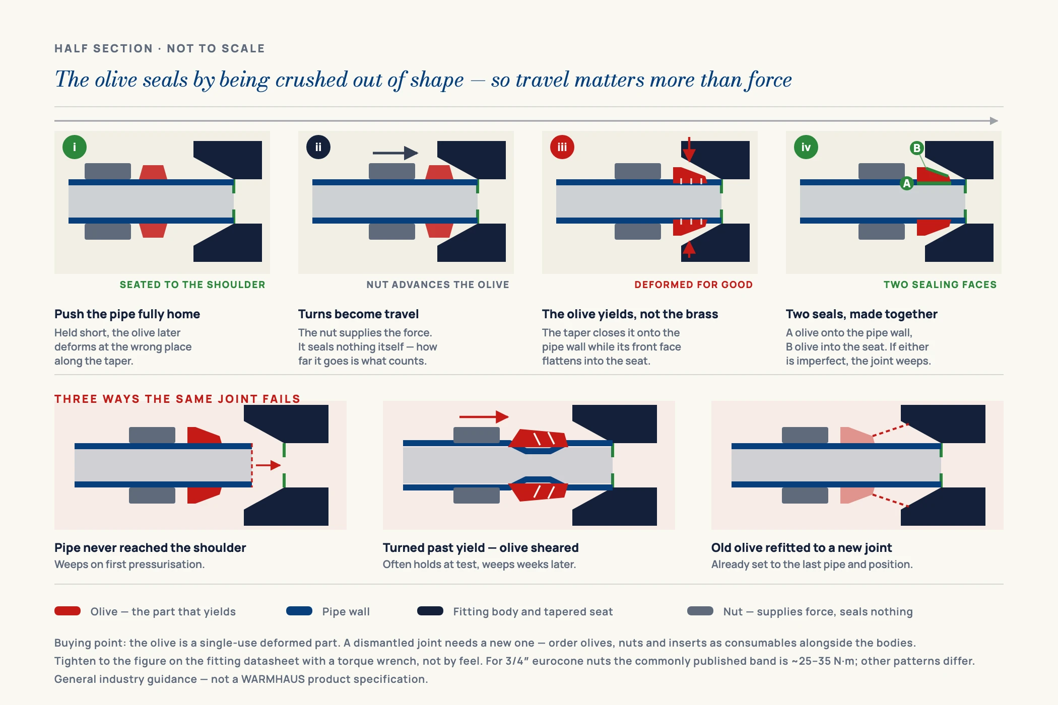
A compression assembly is four parts: the body with a machined tapered seat, the olive, the nut, and — on plastic and multilayer pipe — a support insert inside the bore. As the nut is turned onto the body thread it drives the olive into the taper, which closes the olive radially so it bites the pipe wall while its front face is pressed into the seat. Two seals form at once, and both must work: olive-to-pipe and olive-to-body.
The nut does not seal anything. It only supplies the force that makes the olive seal — which is why turning it harder eventually makes things worse, not better.
Three consequences follow directly. First, the outside diameter of the pipe is the controlling dimension — the fitting never touches the bore, so wall thickness is irrelevant to the seal and a fitting sized for 15 mm copper will not seal on 16 mm plastic. Second, the pipe must be stiff enough to resist the inward squeeze; a plastic or multilayer pipe collapses under the olive unless an insert holds the wall out. Third, the pipe end must be cut square and undamaged, because the olive needs a clean cylindrical surface to bite into — a scored, ovalised or angled end leaves a leak path no amount of torque will close.
This is also why compression is specified where a fusion joint is impractical rather than as a general alternative to it. On a PPR run the pipework itself is welded — our guide to hot-melt welding covers that method — and compression appears only where the system meets a valve, a meter, a manifold tail or a pipe of another material.
II. Size and Thread Reference Table
The two numbers that define a compression fitting are the pipe outside diameter it accepts and the thread on its other end. They are independent: a fitting can take 16 mm pipe on one side and carry a 1/2" male thread on the other. Metric fittings are designated by the pipe OD in millimetres; imperial fittings by the nominal copper tube size. The table below sets out the pairings encountered most often in hot and cold water and heating work.
| Pipe OD accepted | Common designation | Typical mating thread | Insert needed | Typical application |
|---|---|---|---|---|
| 15 mm | 1/2" copper tube | 1/2" BSP male / female | No — rigid copper | Service valves, tap tails, meter sets |
| 16 mm | 16 × 2.0 multilayer / PEX | 1/2" BSP or eurocone 3/4" | Yes | Underfloor loops, radiator tails |
| 20 mm | 20 × 2.0 multilayer / PEX | 1/2" or 3/4" BSP | Yes | Branch runs, manifold connections |
| 22 mm | 3/4" copper tube | 3/4" BSP male / female | No — rigid copper | Risers, cylinder and boiler connections |
| 25 mm | 25 × 2.5 multilayer / PEX | 3/4" or 1" BSP | Yes | Sub-mains, plant room distribution |
| 28 mm | 1" copper tube | 1" BSP male / female | No — rigid copper | Primary circuits, larger risers |
| 32 mm | 32 × 3.0 multilayer / PEX | 1" or 1-1/4" BSP | Yes | Riser transitions, manifold inlets |
| 40 mm | 40 × 3.5 multilayer / PEX | 1-1/4" or 1-1/2" BSP | Yes | Distribution mains, plant connections |
Values are general industry guidance, not a WARMHAUS-specific specification. Wall thicknesses, insert dimensions and thread pairings vary by pipe family and fitting design, and metric and imperial sizes that appear close (15 mm and 16 mm, 22 mm and 20 mm) are not interchangeable. Always confirm against the datasheet supplied with the fitting and the pipe you are using.
Two points on that table matter when you are placing an order rather than working on site. Thread form matters as much as thread size: BSP parallel and BSP taper are both called 1/2", but a parallel male thread seals on a washer or O-ring at the face while a taper thread seals on the flanks with a sealant — fitting one where the other is expected produces a joint that looks assembled and weeps under pressure. And near-miss diameters are the classic stocking error: boxes that differ by one millimetre get mixed on a van shelf. Specify both numbers on every line of a purchase order.
III. Choosing the Support Insert
On copper the pipe is its own support. On PEX, PE-RT and multilayer pipe it is not: the olive would squash an unsupported wall inward, the pipe would relax over the following weeks, and the joint would loosen and weep long after the installer had left. The support insert — a thin-walled sleeve pushed into the pipe bore before the fitting is made up — carries that load and keeps the wall round under the olive.
Inserts are not generic. Their outside diameter must match the bore of the specific pipe, which means an insert for 16 × 2.0 pipe does not suit 16 × 2.2 pipe even though both are called 16 mm. Get this wrong in either direction and it shows: an undersized insert leaves the wall unsupported and the joint relaxes; an oversized one will not seat, and forcing it swells the pipe end so the nut will not start. Stainless steel inserts are used where the fitting will see repeated dismantling or higher temperatures; plain brass is common elsewhere. Either way, the insert must be pushed fully home until its collar sits against the pipe end — a partly inserted sleeve supports the wrong part of the pipe and leaves the olive squeezing on nothing.
Because insert selection is tied to the exact pipe dimension, order fittings and pipe as a matched set. The dimensional relationships behind this are covered further in our reference on pipe dimensions and pressure classes.
IV. Making the Joint: The Method That Works
Compression is an easy joint to make badly and a straightforward one to make correctly. The difference is a fixed sequence, followed the same way every time.
Cut the pipe square and deburr it
Use a rotary pipe cutter, not a hacksaw. An angled cut presents an elliptical section to the olive and guarantees a leak path. Deburr the inside edge so the insert enters cleanly and the bore is not restricted, and clean the outside for at least the length the olive will sit on — a scratch that runs lengthwise under the olive is a channel, and no amount of tightening closes it.
Fit the nut and olive in the right order and orientation
Nut first, open end facing the fitting body, then the olive. Olives with a tapered profile are directional — the taper faces the body seat. Fitting one backwards produces a joint that appears to tighten normally and never seals properly. On plastic or multilayer pipe, push the support insert fully home at this point, before the pipe goes anywhere near the body.
Seat the pipe fully into the body before tightening
Push the pipe in until it stops against the internal shoulder and hold it there while you start the nut. A pipe held short means the olive deforms in the wrong place along the taper; a pipe held at an angle means it deforms unevenly and seals on one side only. Start the nut by hand for several turns to confirm the threads have engaged straight — a cross-threaded nut in brass strips easily and is not recoverable.
Tighten to the fitting’s stated figure — then stop
Hold the body with a second spanner so the torque goes into the joint rather than twisting the pipework behind it. Tighten to the value on the fitting datasheet. Where no figure is given, the widely used field method is hand-tight plus a defined part-turn with a spanner, but that is a rule of thumb, not a specification, and it varies with size and material. Confirm the figure for your fitting before relying on it.Torque figures for specific fittings: available on request.
Pressure-test before anything is concealed
Test the joint under pressure while it is still accessible. One that weeps slightly on first pressurisation can often be corrected with a small additional turn; one that weeps after a wall has been closed cannot be reached. Never bury or box in a compression joint that has not held test pressure, and keep these joints accessible in service wherever the design allows.
V. The Failure Modes and What Each One Tells You
Nearly every compression complaint reduces to a small number of causes, and each announces itself differently. Reading the symptom saves dismantling the wrong joint.
Overtightening is the most common and the most counter-intuitive, because the instinct on finding a weep is to turn the nut further. Past a certain point the olive stops deforming and starts shearing: the ring extrudes along the pipe, the wall thins beneath it, and on plastic pipe it can be cut through entirely. An overtightened joint often seals initially and fails weeks later. The tell is a deeply grooved or split olive on dismantling, and a pipe with a visible waist where it sat.
Undertightening gives an immediate steady weep on first pressurisation, and is genuinely recoverable — a controlled further part-turn usually stops it. A missing or wrong insert produces the delayed failure: solid at test, weeping after a few weeks as the unsupported wall relaxes under the olive. Reusing an olive is the fourth: it has already deformed to one pipe at one position and rarely reseals reliably on a fresh assembly.
One more, seen mainly on mixed systems: dezincification, the selective leaching of zinc from brass in aggressive water, which leaves a porous, weakened structure. It is a water chemistry and alloy question rather than an installation error, and the answer is specifying a suitable brass grade for the water in that market — worth raising at the specification stage, particularly where fittings will be concealed and cannot be inspected.
VI. Specifying Compression Fittings for Stock
For a distributor, compression is a range problem more than a product problem. The fittings are individually inexpensive and mechanically simple, but the matrix is wide: each pipe OD has to be available against several thread sizes, in straight, elbow, tee and adaptor bodies, in male and female variants, with matching olives, nuts and inserts alongside them. A range that is complete except for one common combination sends the installer to another counter for the whole order.
Two decisions cut most of the complexity. Decide first which pipe families your market actually installs — metric plastic, imperial copper, or genuinely both — because that determines whether you stock one dimensional series or two that must never be confused on the shelf. Then decide where the thread interfaces sit: valves, manifolds and appliances set the thread sizes you must be able to meet, and those points are where compression earns its place. Our pipe tools and accessories page covers the cutters and ancillary items that belong in the same order.
VII. Buying Brass Compression Fittings From a Manufacturer
WARMHAUS is a manufacturer of PPR, PEX and brass piping systems — not a trading company. The machining lines that produce our brass bodies, olives and nuts are our own, which is what makes the dimensional consistency of the compression seat something we control rather than something we inspect on arrival. Compression sealing depends on the fit between three machined surfaces and a pipe, so that consistency is the whole product. Our complete brass system — compression and threaded fittings, ball valves and manifolds — is machined to one internal standard, so the thread on a valve and the thread on the adaptor that meets it come from the same specification rather than from two suppliers’ interpretations of it.
Manufacturing since 1993 across three plants with over 500 staff, ISO 9001 / ISO 14001 / ISO 45001 certified, EU CE marked and SGS tested. Raw material is sourced from Hyosung, Borealis and LG on the polymer side, with 57-3 and CW617 brass on the metal side. No MOQ — which matters more on compression fittings than almost anywhere else in a catalogue, because a usable range means many size-and-thread combinations in small quantities rather than a container of one line. Standard lead time is 45 days from confirmed order, planned into production slots. Request the brass compression fittings size and thread matrix, plus distributor terms — tell us which pipe outside diameters and thread sizes your market works in and we will send the matching range. Certificate documents and test documentation: available on request.